Drawing and processing apparatus

A technology for deep processing and tools, which is applied in the field of deep drawing processing equipment, can solve the problems of increased installation space, slow processing speed, and increased cost, and achieve the effects of correct and simple rotation control, shortened cycle time, and suppressed costs

Inactive Publication Date: 2008-12-24
NIHON SPINDLE MFG CO LTD
View PDF1 Cites 2 Cited by
  • Summary
  • Abstract
  • Description
  • Claims
  • Application Information

AI Technical Summary

Problems solved by technology

[0012] In this drawing processing device, compared with the conventional drawing processing device in which the workpiece W is fixed, since the workpiece W is mounted on the spindle, the rotation speed of the workpiece W is increased, and the processing speed is increased. Therefore, there is a problem that the surface of the workpiece W needs to be plastically processed multiple times, and the overall processing speed becomes slower (the cycle becomes longer).
[0013] In order to deal with such a problem, although it is conceivable to arrange a plurality of squeeze rolls R facing each other in a direction perpendicular to the axis A, there is a need to arrange tool mounting mechanisms (in the illustration, a lifter) according to the number of squeeze rolls R Frame and right-angle direction movement mechanism), the installation space increases and the cost increases

Method used


Image

  • Drawing and processing apparatus
  • Drawing and processing apparatus
  • Drawing and processing apparatus

Examples


Embodiment 1

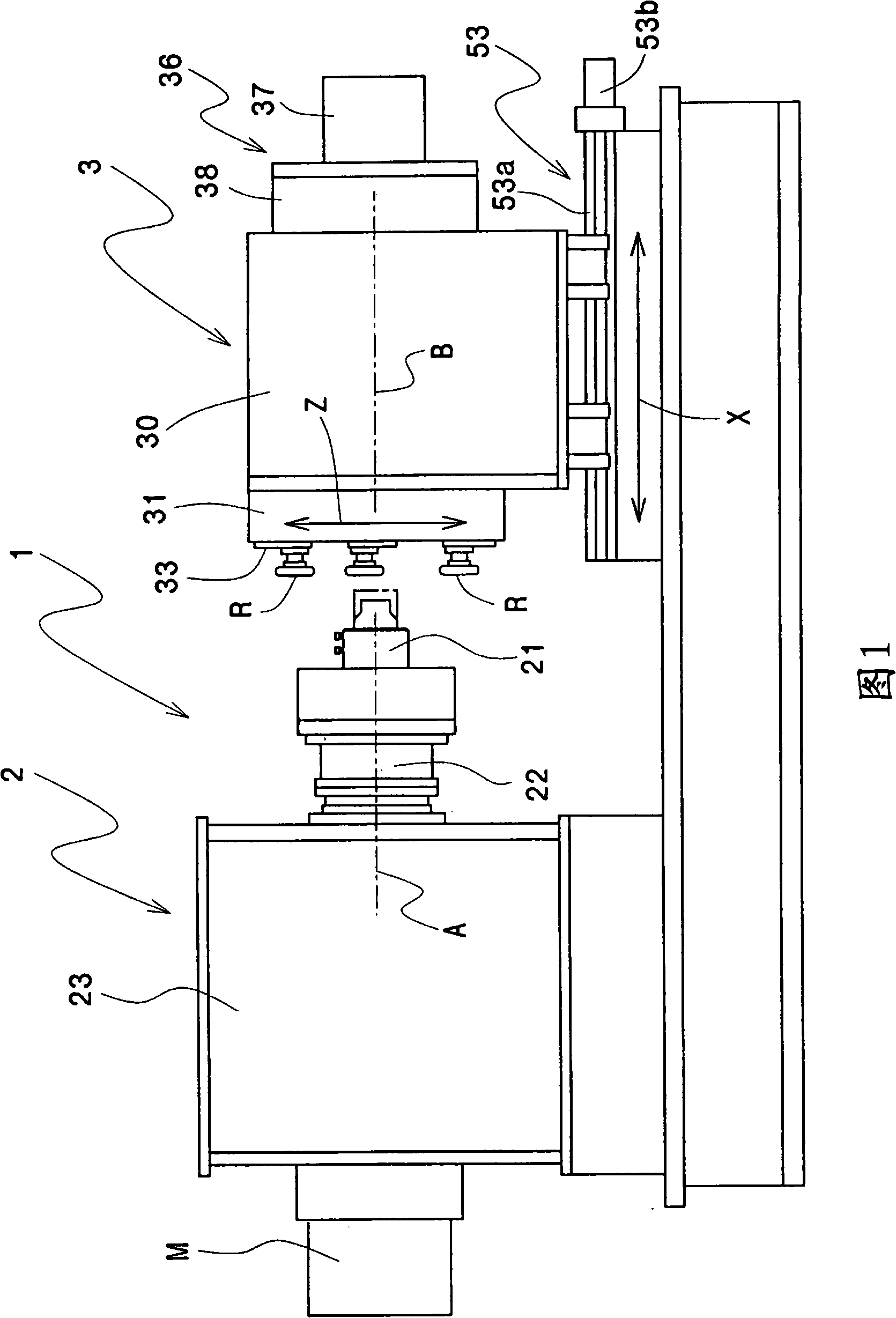
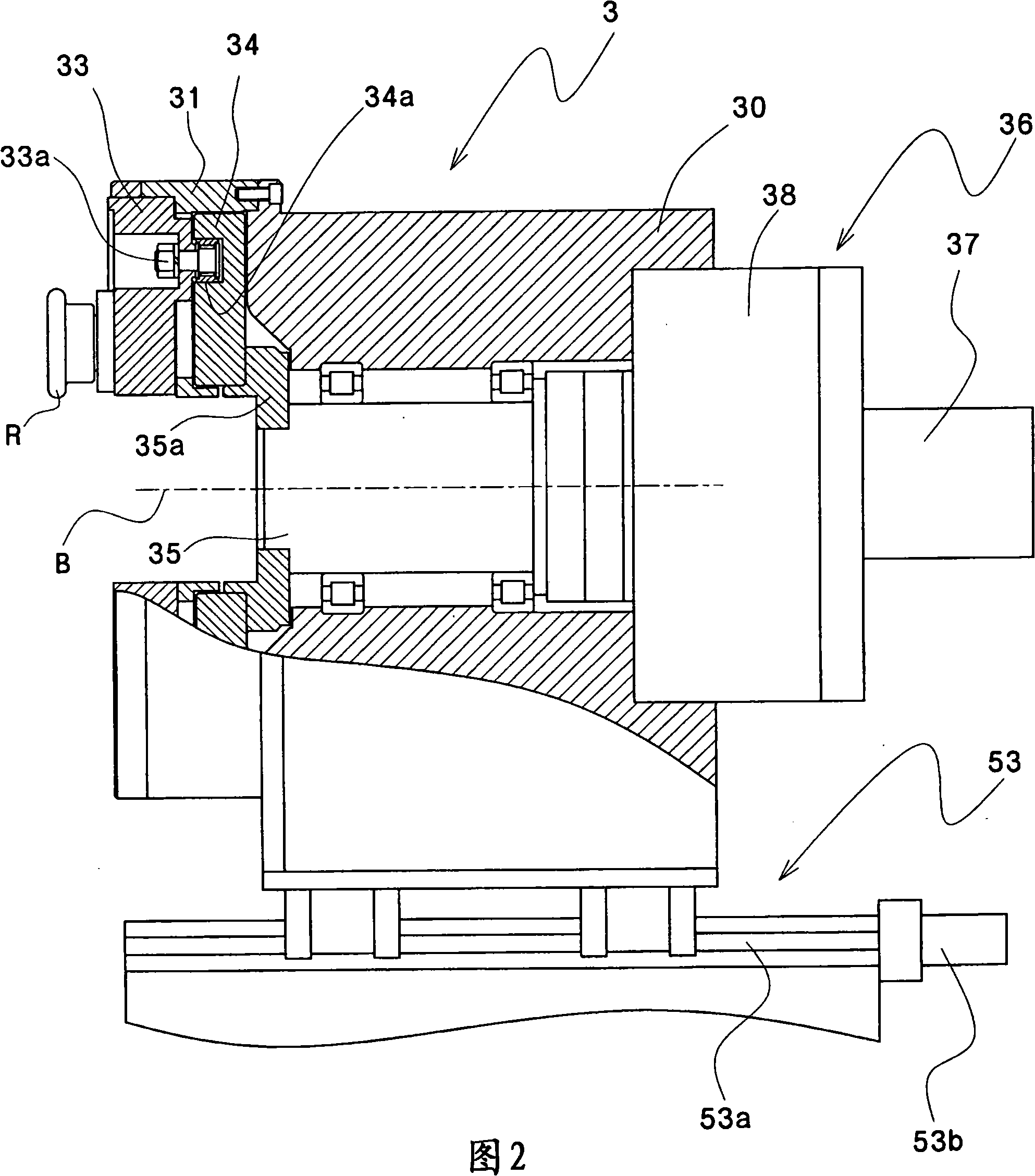
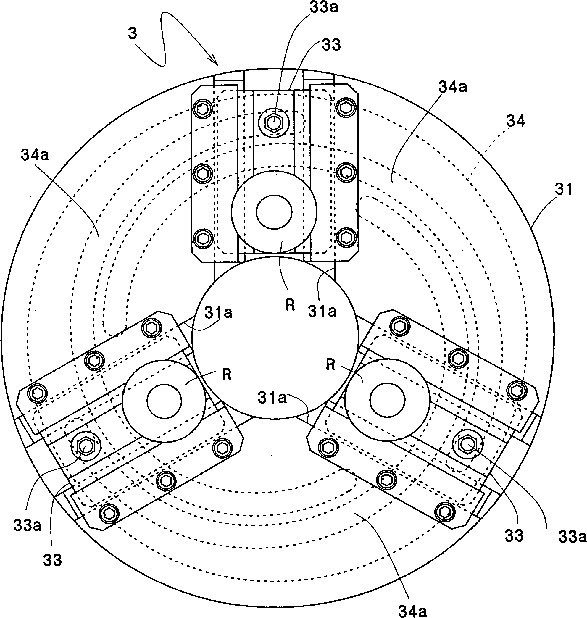
[0034] Figure 1~ Figure 4 An example of the drawing processing device of the present invention is shown.

[0035] This drawing machine 1 has a spindle mechanism 2 and a tool mounting mechanism 3 to which a squeeze roll R provided facing the spindle mechanism 2 is mounted, as in the prior art example.

[0036] The front end of the spindle mechanism 2 is equipped with a holding mechanism 21, which is used to hold and fix the cylindrical workpiece W, and is installed so that the axis center of the workpiece W coincides with the axis A of the spindle mechanism 2. .

[0037] Furthermore, the tool mounting mechanism 3 is composed of a cylindrical main body 30, a panel 31 arranged on a side surface of the main body 30, and a plurality of parts arranged on the panel 31 so as to be movable in a direction perpendicular to the axis A of the main shaft 22. A roller mounting table 33, a cam plate 34 engraved with a helical groove 34a for fitting a guide pin 33a protruding from the rolle...


PUM


Abstract

A stretching processing device, used for carrying out excellent stretching process with a plurality of extruding rollers at high efficiency as a device for processing with work piece revolution; the stretching processing device (1) is composed of a main shaft mechanism (21) having a holding mechanism (21) disposed on fore end of the main shaft (22) and used for holding work piece W, and a tool installation mechanism (3) configured same as the main shaft mechanism (2). The tool installation mechanism (3) is composed of a cylindrical main body (30), a panel (31) disposed on sidewall of the main body (30), a plurality of roller installation floors (33) movably disposed on the panel (31) at right angle direction relative to axes (A) of the main shaft (22), cam plates (34) etched with helical grooves (34a) to be meshed with guiding pins (33a) protruding from the roller installation floors (33), and a rotary driving mechanism (36) for driving the cam plates (34) to rotate; with rotation of the cam plates (34), the roller installation floors (33) can move along right angle direction relative to axes A of the main shaft(22).

Description

technical field [0001] The present invention relates to a drawing processing device, and more particularly, to a drawing processing device that presses a squeeze roller against a workpiece mounted on a front end of a rotating spindle to perform drawing processing. Background technique [0002] Conventionally, as a drawing device for drawing a cylindrical member such as a pipe tip, there is a drawing device previously proposed by the present applicant. Thereby, drawing processing is performed on the front end of a fixed tube to be processed (hereinafter referred to as "work") (for example, refer to Patent Document 1). [0003] When the workpiece is fixed for deep drawing, although it has the advantage that the axis of the workpiece can be eccentric or inclined relative to the axis of the main shaft for deep drawing, it is necessary to arrange a squeeze roll mounting table, a squeeze roll, and a tool for use on the main shaft. Because of the helical grooved cam plate and the ...

Claims


Application Information

Patent Timeline
Patent Type & Authority Applications(China)
IPC IPC(8): B21D22/16B21D37/00
Inventor 小岛宏大见忍
Owner NIHON SPINDLE MFG CO LTD
Why Eureka
Try Eureka