
Thermal sensitive printer head and method for producing the same

A thermal printing head and manufacturing method technology, applied in printing and other directions, can solve the problems of uneven temperature distribution curve of heating body, affecting the clarity of printed text and graphics, and irregular shape of pixel points, so as to reduce tailing phenomenon, Good thermal conductivity, shape-improving effect

Inactive Publication Date: 2008-12-24
SHANDONG NEW BEIYANG INFORMATION TECH CO LTD
View PDF0 Cites 2 Cited by
  • Summary
  • Abstract
  • Description
  • Claims
  • Application Information

AI Technical Summary

Problems solved by technology

At the same time, due to the mutual influence of heat generated by adjacent heating bodies, the temperature distribution curve in one heating body is not flat, and the shape of pixels is irregular, which affects the clarity of printed text and graphics.
In addition, due to the short printing cycle and short heat dissipation time during high-speed printing, the heat accumulation of the heating element is serious, resulting in smearing and reduced printing quality.

Method used


Image

  • Thermal sensitive printer head and method for producing the same
  • Thermal sensitive printer head and method for producing the same
  • Thermal sensitive printer head and method for producing the same

Examples


Embodiment Construction

[0020] Below in conjunction with accompanying drawing, the present invention is further described.

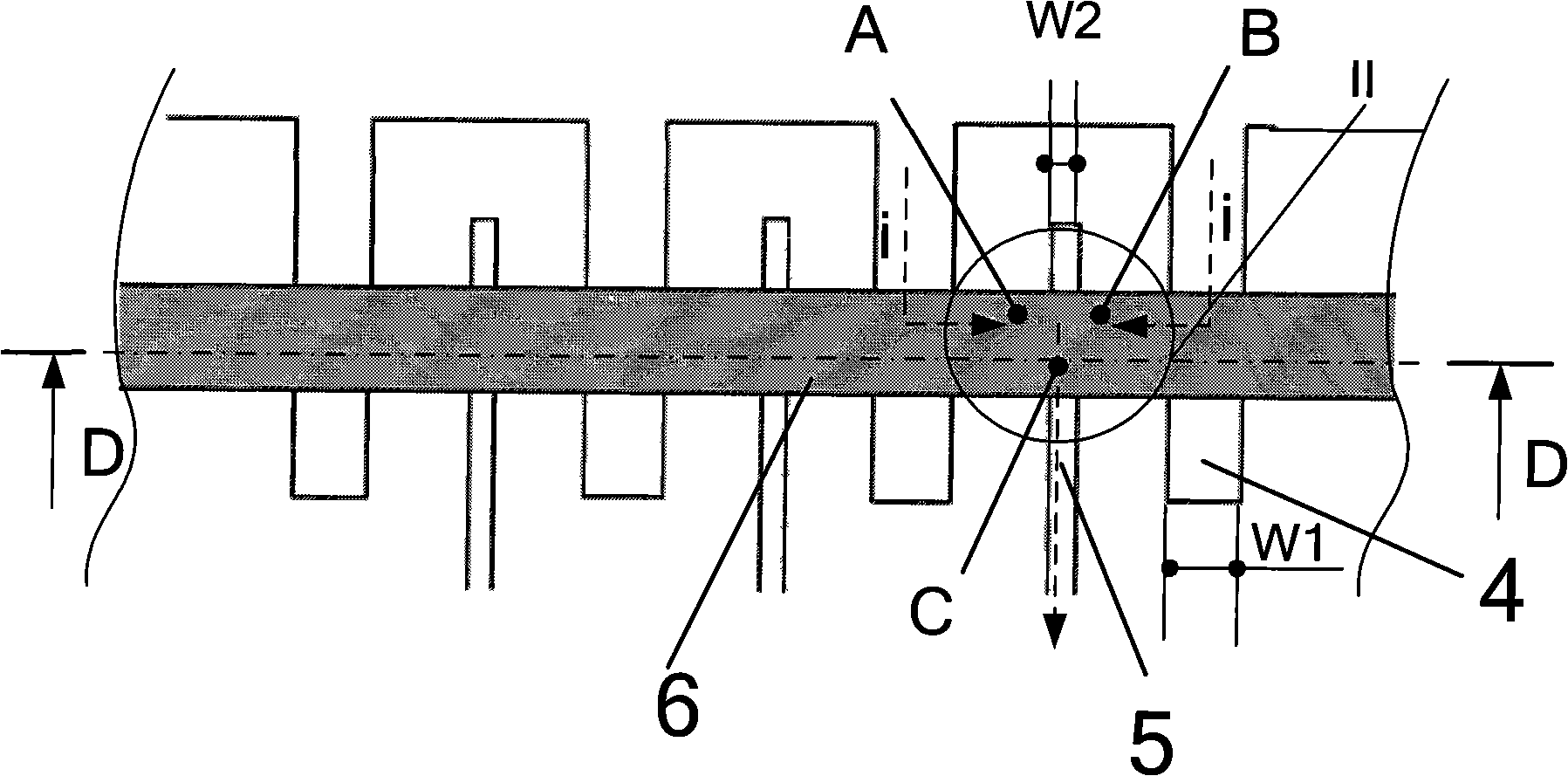
[0021] image 3 It is a schematic diagram of the local structure of the printing head of the present invention. Figure 4 yes image 3 A-A sectional view is shown. Combine below image 3 , Figure 4 The structure of the print head of the present invention will be described. Such as image 3 As shown, the structure of the print head of the present invention includes: a common electrode 4 , individual electrodes 5 , and a heating element 6 .

[0022] The common electrode 4 is connected to a power supply to provide energy for the heating element 6 when the print head is working. The width W1 of the common electrode 4 is: 25μm<W1≤50μm, the thickness D1 is 0.2μm<D1≤2.0μm, and the material of the common electrode 4 is metal gold, which has excellent electrical conductivity, thermal conductivity and chemical stability. Ideal material for head electrodes.

[0023] The individu...


PUM


Abstract

The invention relates to a thermal printing head and a manufacturing method thereof. The thermal printing head comprises a ceramic substrate, a printed circuit board, etc. The ceramic substrate is provided with common electrodes, individual electrodes and a heating element. The width of adjacent common electrodes is larger than the width of the individual electrodes, and the thickness of the adjacent common electrodes is larger than the thickness of the individual electrodes. The printing head can effectively improve the shape of printing points, the thermal response speed, the printing quality and the printing speed.

Description

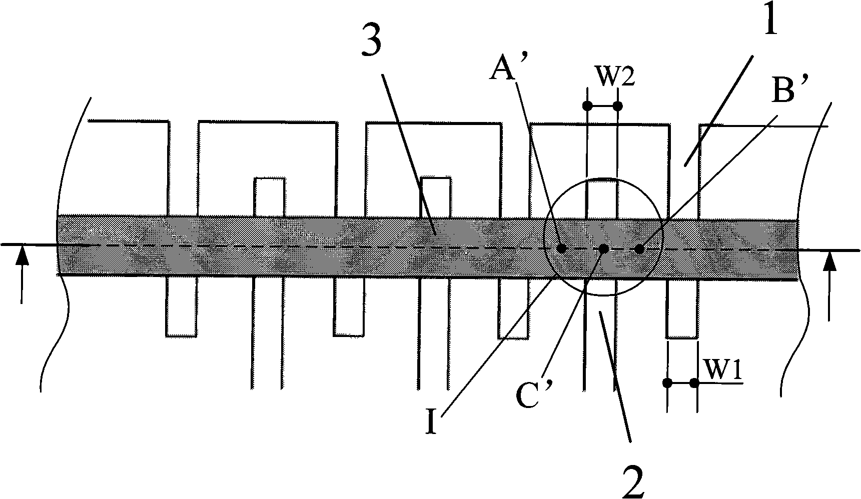
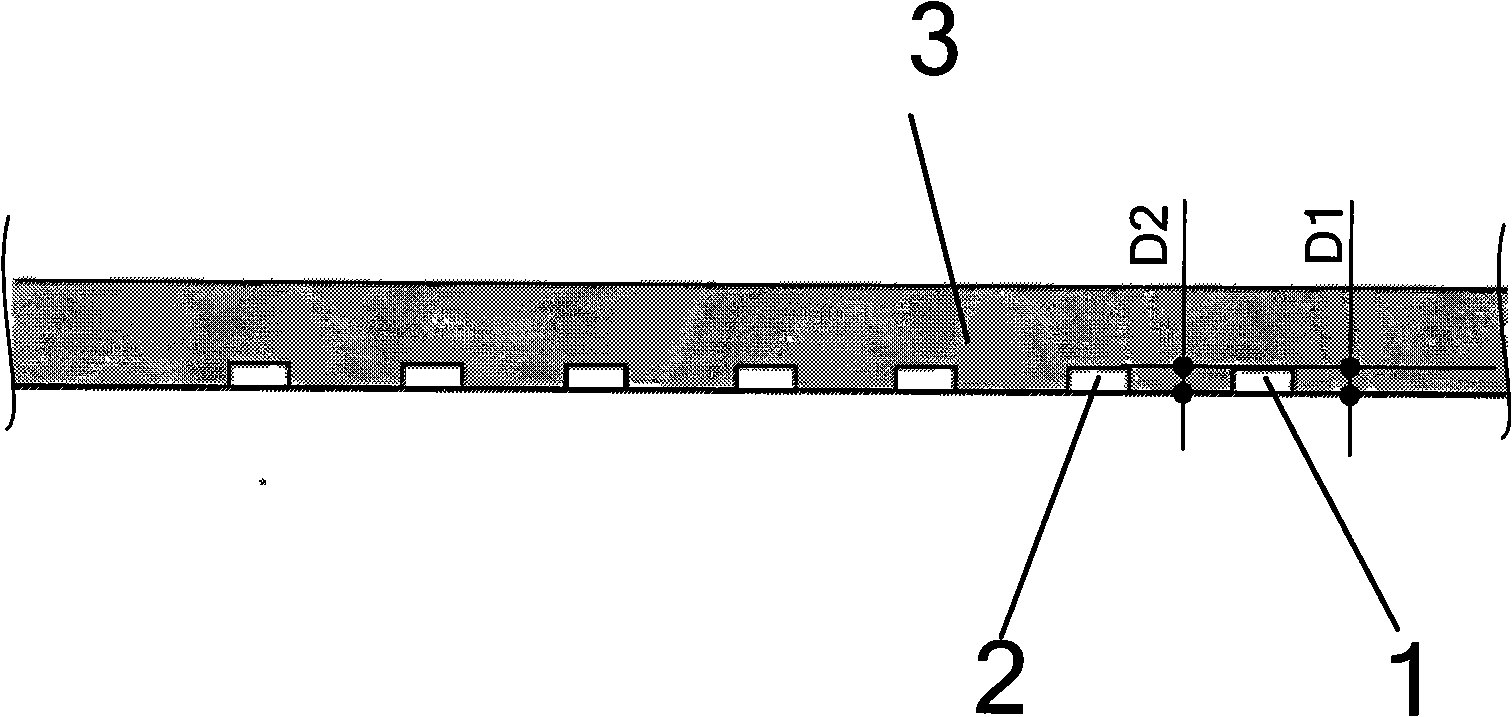
technical field [0001] The invention relates to a thermal printing head and a manufacturing method thereof. Background technique [0002] Generally, the structural wiring of the print head includes individual electrodes and common electrodes. The individual electrodes have the same width and thickness as the common electrodes, and the width of the electrodes is generally 22.5 μm. Such as figure 1 As shown, the heating element 3 is located above the common electrode 1 and the individual electrode 2, and the width W1 of the common electrode 1 is the same as the width W2 of the individual electrode 2, as shown in figure 2 As shown, the thickness D1 of the common electrode 1 is the same as the thickness D2 of the individual electrodes 2 . Since the heating element 3 is a continuous straight line, the dots printed by the print head with this structure are often connected together. At the same time, due to the mutual influence of heat generated by adjacent heating bodies, the...

Claims


Application Information

Patent Timeline
Patent Type & Authority Applications(China)
IPC IPC(8): B41J2/345B41J2/335
Inventor 王永华
Owner SHANDONG NEW BEIYANG INFORMATION TECH CO LTD
Learn More