Coal mine mash gas incineration torch

A coal mine gas and torch technology, applied in the field of coal mine gas incineration equipment, can solve the problems of gas emptying, air pollution, equipment personal and property losses, etc., and achieve the effect of protecting mine safety

Inactive Publication Date: 2008-12-24
SHENGLI OIL FIELD SHENGLI POWER MACHINERY GRP
View PDF0 Cites 22 Cited by
  • Summary
  • Abstract
  • Description
  • Claims
  • Application Information

AI Technical Summary

Problems solved by technology

[0002] The traditional method of gas treatment in coal mining is direct discharge, but this method has the following disadvantages or deficiencies: ①The average concentration of the gas drained is currently lower than 30%, and for the gas with a gas concentration higher than 30%, due to civil Intermittent and discontinuous utilization means such as power generation or power generation, causing some gas to be directly emptied, ...

Method used


Image

  • Coal mine mash gas incineration torch

Examples


Embodiment Construction

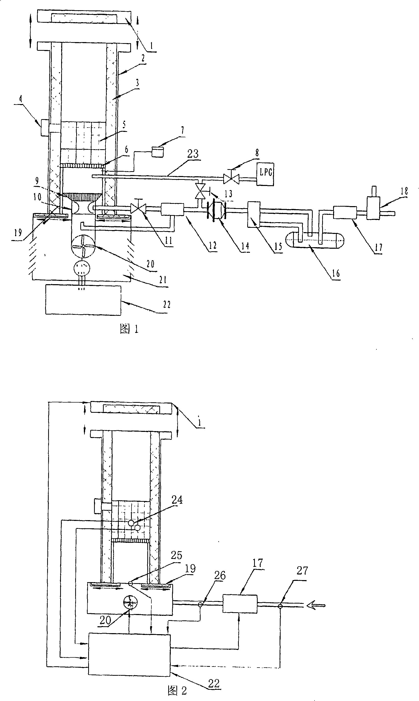
[0012] As shown in Figure 1 and Figure 2, a coal mine gas incineration flare includes a burner, a gas delivery pipeline system, an air supply system, an electronic ignition system and an electrical control system. The burner includes the outer shell 2 and the insulation layer 3 installed inside, the heat storage honeycomb ceramic 5 installed in the middle of the insulation layer and its support 6, the proportional mixer 10 and the multi-head mixed gas nozzle 9 installed at the bottom of the support, and the upper end of the housing 2 The upper sealing cover 1 installed, the lower sealing cover 19 and the base 21 installed at the lower end of the housing 2. The gas delivery pipeline system includes the pipeline connected with the proportional mixer 10, the main gas supply valve 11 and the pressure regulating valve 12, the flame arrester 14, the filter dehydrator 15, the water seal flame arrester 16, the electric control valve 17 and the gas Bleed valve 18. The air supply syste...


PUM


Abstract

The invention discloses a coal-mine gas-burning torch which comprises a burner and etc. systems including an insulation layer arranged inside a casing; a regenerative honeycomb ceramics and a bracket thereof which are arranged in the middle of the insulation layer, a proportioning mixer and a multi-head mixed-gas nozzle which are arranged on a lower part of the bracket; an upper sealing cover arranged at the upper end of the casing and a lower sealing cover and a base which are arranged at the lower end of the casing; a pipeline and a main gas supply valve which are connected with the proportioning mixer; a pressure-regulating valve, a flame arrester, a filtering dehydrator, a hydroseal flame arrester, an electronic-control valve and a gas diffusion valve which are sequentially connected; a fan which is arranged inside the base under the casing and connected with the lower part of the proportioning mixer; an electronic ignition system comprising an LPG fuel supply valve, a gas supply valve connected with a gas transferring pipeline and an electronic igniter communicated with the lower part of the burner; a temperature sensor arranged in the regenerative honeycomb ceramics; an air pressure sensor arranged at the back of the fan; a gas concentration sensor, a gas pressure sensor and an electronic-control valve which are arranged in the gas transferring pipeline system and a controller arranged on the lower part of the casing.

Description

1. Technical field [0001] The invention relates to coal mine gas incineration equipment, in particular to a coal mine gas incineration flare. 2. Background technology [0002] The traditional method of gas treatment in coal mining is direct discharge, but this method has the following disadvantages or deficiencies: ①The average concentration of the gas drained is currently lower than 30%, and for the gas with a gas concentration higher than 30%, due to civil Intermittence and discontinuity of utilization methods such as power generation, etc., cause some gas to be directly emptied, polluting the atmospheric environment. ②Because the gas drainage changes with underground coal mining activities, its gas concentration also changes all the time, and the concentration may approach or enter the explosion limit of 5% to 15%. For example, the gas is destroyed by directly igniting the gas at the gas outlet There is a big safety problem in the methane, and the lack of treatment will ...

Claims


Application Information

Patent Timeline
IPC IPC(8): F23G7/06F23D14/38F23D14/48F23D14/62F23D14/60
Inventor 马晓钟陈宜亮杨凯
Owner SHENGLI OIL FIELD SHENGLI POWER MACHINERY GRP
Why Eureka
Try Eureka