
Discharge lamp

A discharge lamp and electrode technology, which can be applied to discharge lamps, gas discharge lamps, high pressure discharge lamps, etc., can solve the problems of complicated processing and deterioration of manufacturing efficiency.

Active Publication Date: 2008-12-24
ORC MFG
View PDF4 Cites 9 Cited by
  • Summary
  • Abstract
  • Description
  • Claims
  • Application Information

AI Technical Summary

Problems solved by technology

When the number of grooves is large, the processing is significantly complicated, resulting in deterioration of manufacturing efficiency

Method used


Image

  • Discharge lamp
  • Discharge lamp
  • Discharge lamp

Examples


Embodiment

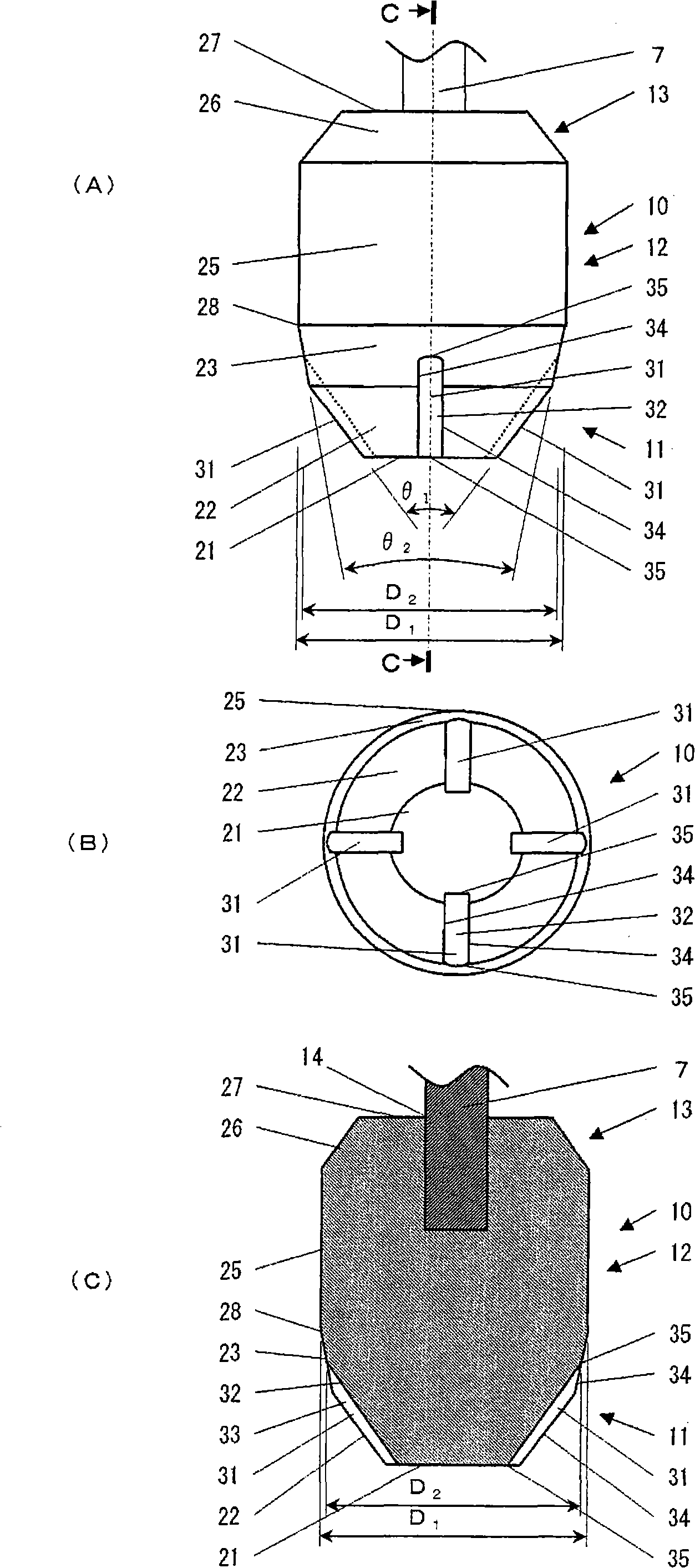
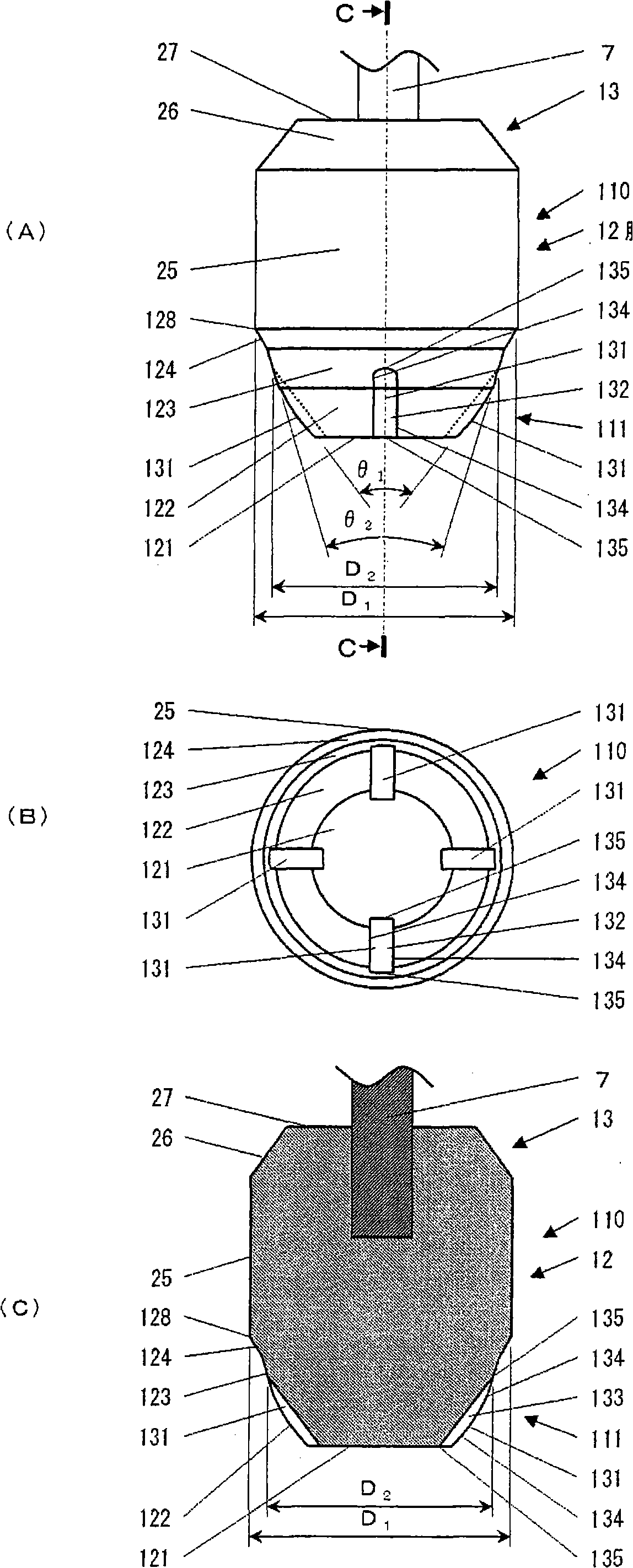
[0026] The anode used in the embodiments of the present invention is: in the range from the front end surface to the taper section, the extension line of the groove neither intersects the main body nor the front end, and is thinner than the main body. A plurality of radial grooves are provided on the side surface.

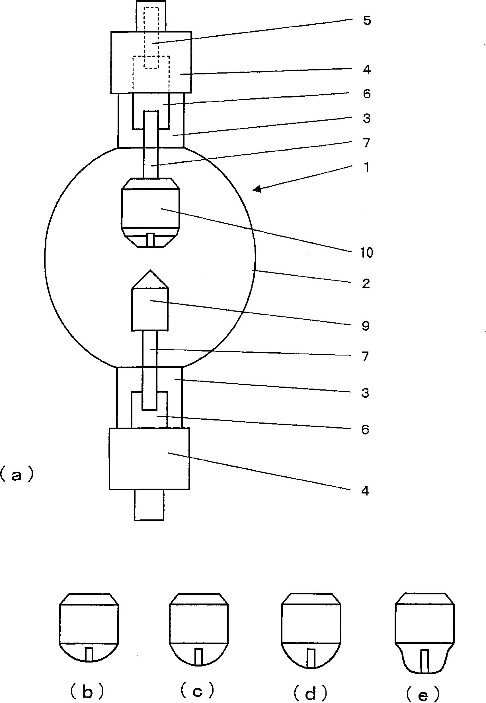
[0027] figure 1 It is an external view of a discharge lamp using an anode according to an embodiment of the present invention, and is a conceptual view showing an electrode shape. exist figure 1 Among them, the discharge lamp 1 is a lamp that discharges between internal electrodes. The light emitting part 2 is a part that emits light by discharge between electrodes, and is a glass member that seals the electrodes to form a discharge space. The sealing tube portion 3 is a portion that hermetically seals the bulb. The base 4 is a part for mechanically holding the lamp and supplying power. The discharge lamp 1 is fixed on the light source device through the lam...


PUM


Abstract

The present invention provides a discharge lamp, which can prevent lamp component from damage caused by the slot part edge of the anode of the discharge lamp for heat radiation. Two or three cones are formed between the front end surface and the main surface of the anode (10). The second inclination from the front end surface of the cone opposite to the axis is minimum and the third inclination is maximum. A plurality of radial slot parts are arranged till to the second cone region. The main surface has no slot part edge, because the slot part does not arrive to the main surface of the anode (10). In the assembling working procedure of the discharge lamp (1), even the main surface contacts with the lamp component, the slot part edge can not damage the lamp component. The slot part is used for inhibiting rock of an arc, and for preventing lamp from blackening due to the heat radiation effect can inhibit consumption of the anode, thus prolonging the service lifetime of the discharge lamp, and the slot part can also be a safe part during assembling working procedure.

Description

technical field [0001] The present invention relates to a discharge lamp such as a short arc type which irradiates ultraviolet rays, and particularly relates to an electrode structure in which radial grooves for heat dissipation are provided on the tapered portion of the electrode tip of the discharge lamp. Background technique [0002] Conventionally, when forming a semiconductor wiring pattern, a discharge lamp such as a short-arc type has been used as a light source for irradiating ultraviolet rays. In this discharge lamp, the anode is held in a discharge space by a sealed tube made of quartz via an electrode rod, and the anode is vertically lit for use in a state where the anode is turned up or down. When the discharge lamp is turned on, the electrons sent from the cathode collide with the anode and become a high-heat state, and the cathode evaporates and is consumed. When the electrodes are worn out, blackening occurs on the inner wall of the discharge lamp due to heat...

Claims


Application Information

Patent Timeline
IPC IPC(8): H01J61/073
CPCH01J61/06H01J61/0675H01J61/0732H01J61/0735H01J61/84H01J61/86
Inventor 林武弘
Owner ORC MFG
Learn More