Method for forming pattern, method for manufacturing electro-optical device, and method for manufacturing electronic device

An electro-optical device and pattern technology, applied in conductive pattern formation, printed circuit manufacturing, optics, etc., can solve problems such as rising costs and unsatisfactory material saving

Active Publication Date: 2008-12-24
SEIKO EPSON CORP
View PDF2 Cites 11 Cited by
  • Summary
  • Abstract
  • Description
  • Claims
  • Application Information

AI Technical Summary

Problems solved by technology

[0008] The technology described in the above-mentioned patent documents has a problem of cost increase due to the use of expensive exposure machines, photomasks, and laser light sources
In addition, since the lyophobic material that is necessary only for the non-pattern surface is applied to the entire substrate, it is not ideal from the viewpoint of material saving.

Method used


Image

  • Method for forming pattern, method for manufacturing electro-optical device, and method for manufacturing electronic device
  • Method for forming pattern, method for manufacturing electro-optical device, and method for manufacturing electronic device
  • Method for forming pattern, method for manufacturing electro-optical device, and method for manufacturing electronic device

Examples


Embodiment Construction

[0051] The following will refer to Figure 1 to Figure 19 Embodiments of the pattern forming method, electro-optical device manufacturing method, and electronic device manufacturing method of the present invention will be described.

[0052] In addition, in each drawing used in the following description, in order to make each member into a recognizable size, the scale of each member is changed suitably.

[0053] (droplet ejection device)

[0054] First, a droplet discharge device used in the pattern forming method of this embodiment will be described.

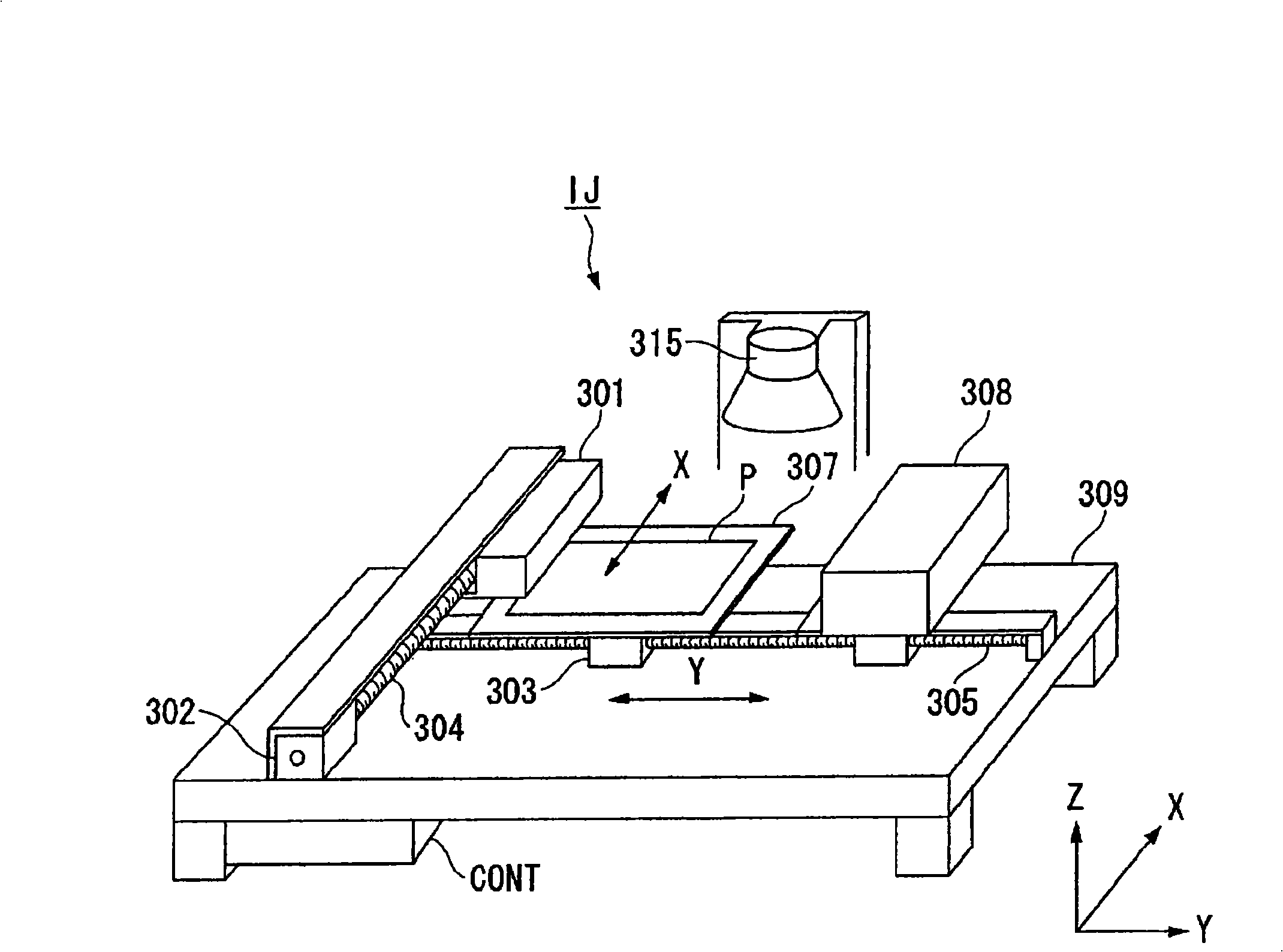
[0055] figure 1 is a schematic configuration diagram of the droplet ejection device.

[0056] The droplet ejection device (ink jet device) IJ is a device that ejects (drops) droplets from a droplet ejection head to a substrate P, and includes: a droplet ejection head 301, an X-direction drive shaft 304, a Y-direction guide shaft 305, a control Device CONT, stage 307 , cleaning mechanism 308 , base 309 , heater 315 . The st...


PUM

PropertyMeasurementUnit
particle diameteraaaaaaaaaa
surface tensionaaaaaaaaaa

Abstract

The present invention provides a method for forming pattern which has good quality without increasing cost. The pattern (W) is formed by coating a functional liquid on a substrate (P) having a lyophilic part (Pa) and a lyophobic part (H) relative to the functional liquid. The method comprises: a first working procedure for forming a lyophobic part by coating a droplet containing a lyophobic material to a substrate having a lyophilic part, and a second working procedure for coating a function liquid to a lyophilic part between the lyophobic parts. The lyophobic material comprises a silane compound, a compound including a fluoroalkyl group, and a resin containing fluorine.

Description

technical field [0001] The present invention relates to a method for forming a pattern, a method for manufacturing an electro-optical device, and a method for manufacturing an electronic device. Background technique [0002] In the case of forming a pattern using a droplet discharge method (inkjet method), a liquid droplet (ink) is discharged to hit a predetermined position on a substrate to form a pattern. When the liquid droplets are ejected to hit the substrate in this way, there is a possibility that the hit liquid droplets may be excessively wetted and spread or separated due to the characteristics of the substrate surface. In this case, there arises a problem that a desired wiring pattern cannot be obtained. [0003] Therefore, Patent Document 1 discloses a technique of performing lyophobic processing on the surface of the substrate to be the pattern formation surface, and irradiating the lyophobic processed surface with an ultraviolet laser beam that has passed throu...

Claims


Application Information

Patent Timeline
Patent Type & Authority Applications(China)
IPC IPC(8): H05K3/10H05K3/14G02F1/1362H01L21/00H01L51/00
CPCG02F1/136286H05K3/1208H05K3/125H05K2201/09909H05K2203/013H05K2203/1173H10K71/15H10K71/611B41J2/005G03F7/0045G03F7/0046
Inventor 平井利充
Owner SEIKO EPSON CORP
Why Eureka
Try Eureka