Telescopic shaft for steering a vehicle and motor vehicle steering system

A telescopic shaft and vehicle technology, which is applied to the steering control, steering column, steering control and other directions installed on the car, and can solve the problems of hindering the relative sliding of the male shaft and the female shaft

Inactive Publication Date: 2008-12-31
JTEKT CORP +1
View PDF5 Cites 13 Cited by
  • Summary
  • Abstract
  • Description
  • Claims
  • Application Information

AI Technical Summary

Problems solved by technology

As a result, smooth relative sliding between the male shaft and the female shaft may be prevented

Method used


Image

  • Telescopic shaft for steering a vehicle and motor vehicle steering system
  • Telescopic shaft for steering a vehicle and motor vehicle steering system
  • Telescopic shaft for steering a vehicle and motor vehicle steering system

Examples


Embodiment Construction

[0030] Preferred embodiments of the present invention will be described with reference to the drawings.

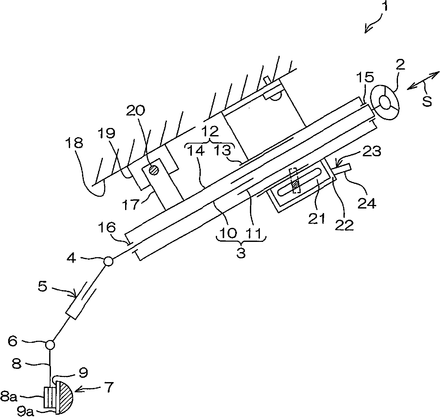
[0031] figure 1 It is a schematic diagram showing a schematic configuration of a vehicle steering device 1 including a vehicle steering telescopic shaft according to an embodiment of the present invention. refer to figure 1 The vehicle steering device 1 has a tilt adjustment function for slightly adjusting the position of a steering member 2 such as a steering wheel up or down relative to a driver. In addition, the vehicle steering device 1 also has a telescopic adjustment function for slightly adjusting the position of the steering member 2 back and forth with respect to the driver.

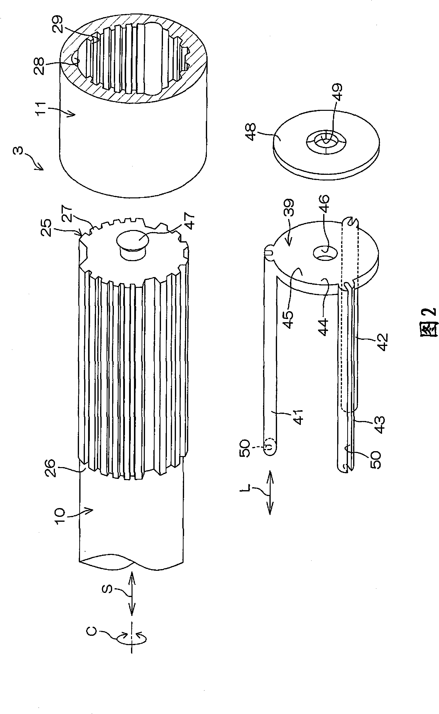
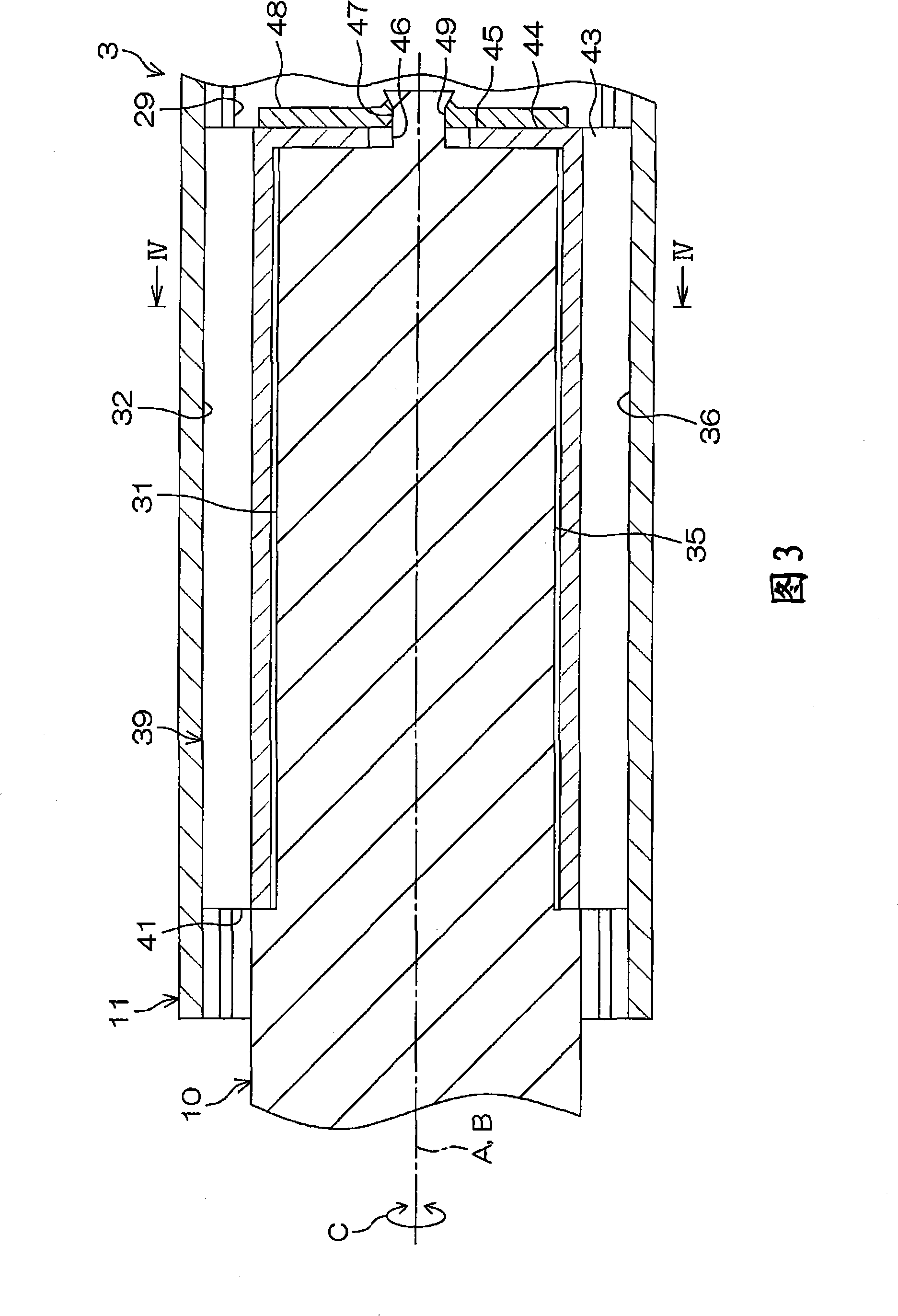
[0032] The vehicle steering device 1 includes a steering member 2 and a steering shaft 3 as a telescopic shaft for vehicle steering. The steering shaft 3 is connected to the steering member 2 and rotates according to the steering of the steering member 2 .

[0033] The steering member 2 ...


PUM


Abstract

A telescopic shaft for vehicle steering includes: an inner shaft and a tubular outer shaft fitted with each other; at least three pairs of axial grooves formed on an outer periphery of the inner shaft and an inner periphery of the outer shaft; a rigid coupling element for rigidly connecting the inner shaft and the outer shaft in a circumferential direction (C) of the inner shaft when a relative phase of the inner shaft and the outer shaft with respect to the circumferential direction (C) exceeds a predetermined range; and a plurality of elongate resin rods as elastic coupling elements for elastically connecting the inner shaft and the outer shaft in the circumferential direction (C) when the relative phase is in the predetermined range. Each of the plural resin rods is formed with a groove. A section of the groove is shaped like U opening toward the outside in a radial direction (U) of the inner shaft.

Description

technical field [0001] The present invention relates to a vehicle steering telescopic shaft and a vehicle steering device. Background technique [0002] A vehicle steering device includes a steering shaft or an intermediate shaft that transmits rotation of a steering member such as a steering wheel (for example, see Documents 1 to 4). [0003] Document 1: Japanese Patent Application Publication No. 2002-539033 [0004] Document 2: Specification of US Patent No. 6620050 [0005] Document 3: Japanese Patent Laid-Open No. 2006-273128 [0006] Document 4: Specification of Japanese Patent No. 3797304 [0007] In the above-mentioned document 2, the male shaft and the female shaft of the intermediate shaft are fitted so as to be relatively slidable in the axial direction and to be able to transmit torque. A plurality of metal pins having a C-shaped cross section are interposed between the male shaft and the female shaft. [0008] For example, since the pin is molded from resin...

Claims


Application Information

Patent Timeline
Patent Type & Authority Applications(China)
IPC IPC(8): B62D1/18
CPCB62D1/185F16C3/035F16C29/02F16C2326/24
Inventor 宫胁尚人吉冈弘至大月俊一
Owner JTEKT CORP
Why Eureka
Try Eureka