
Laser welding narrow butt-jointed seam measurement method and device

A technology of laser welding and butt welding, which is used in measuring devices, optical devices, instruments, etc., and can solve the problems of limited lateral resolution, inconspicuous joint features, and inability to directly obtain surface normal vectors.

Inactive Publication Date: 2008-12-31
HUAZHONG UNIV OF SCI & TECH +1
View PDF1 Cites 46 Cited by
  • Summary
  • Abstract
  • Description
  • Claims
  • Application Information

AI Technical Summary

Problems solved by technology

The butt weld gap of laser welding is narrow and the joint features are not obvious. The horizontal resolution of the existing laser triangulation and binocular vision principle sensors is limited, and it is difficult to extract the position and width information of the weld from the measurement data.
For welds formed by splicing three-dimensional curved surfaces in space, the welding process requires that the welding laser beam be located in the direction of the normal vector of the surface at the center of the weld as much as possible. However, the existing weld seam measurement sensors cannot directly obtain the normal vector of the surface at the center of the weld at the measurement position.
For narrow laser welding seams, the existing sensors cannot simultaneously obtain the three-dimensional position of the weld center, the normal vector of the surface at the center of the weld, and the width of the weld

Method used


Image

  • Laser welding narrow butt-jointed seam measurement method and device
  • Laser welding narrow butt-jointed seam measurement method and device
  • Laser welding narrow butt-jointed seam measurement method and device

Examples


Embodiment Construction

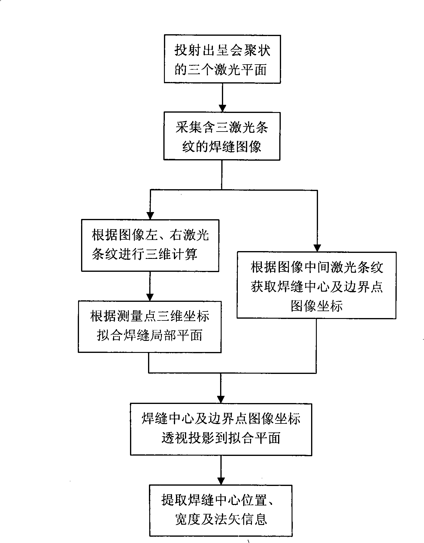
[0023] The three-dimensional coordinates of the weld center, the normal vector of the surface and the measurement method of the weld width are as follows. The internal and external parameters of the telecentric lens CCD camera and the laser planes of the first and third line light source lasers are calibrated. Using the CCD camera and the first and third line light sources The lasers constitute a laser triangulation system; according to the image coordinates of the laser stripe center of the first and third line light source lasers on the image, the three-dimensional coordinates of the corresponding laser stripe center point are obtained by using the principle of laser triangulation. The plane fitting is carried out on the three-dimensional coordinate measurement data of the center points of the laser stripes of the first and third line light source lasers, and the equation of the fitting plane is obtained. Image processing is performed on the laser stripes in the vertical cent...


PUM

PropertyMeasurementUnit
Wavelengthaaaaaaaaaa

Abstract

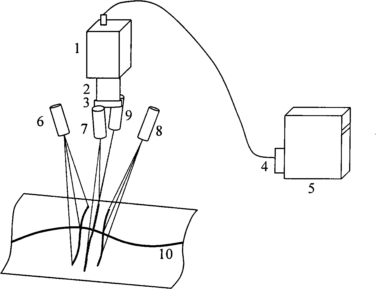
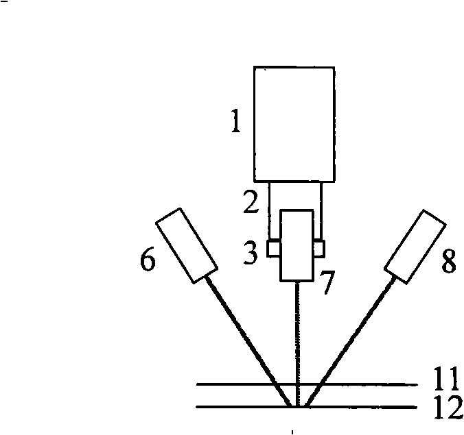
The invention relates to a measuring method of a strictured butt-jointed seam in laser welding, and a device; two-dimension and three-dimension visual information is combined together organically, the information of three-dimension position, normal vector and weld width of a seam center is obtained at a same measurement position by carrying out calibration to a CCD camera and two laser planes and utilizing a seam image containing three laser stripes. The device comprises a telecentric lens, the CCD camera, an image grabbing card, a band-pass filter and a computer. Each linear light source laser projects three converged laser planes, the laser stripes formed by the intersection of all the laser planes and the plane which is vertical to the principal optic axis of the CCD camera are approximately parallel. The first and third linear light source lasers are symmetrically installed on the left and the right sides of the CCD camera and form the angles of 15 degrees to 60 degrees with the principal optic axis of the CCD camera; the second linear light source laser is symmetrically installed at the front side or the back side of the CCD camera and forms the angles of 10 degrees to 30 degrees with the principal optic axis of the CCD camera. The device has simple structure, with rich measurement information.

Description

technical field [0001] The invention belongs to the technical fields of visual measurement technology and laser welding processing, and in particular relates to a method and device for measuring narrow butt welds in laser welding. Background technique [0002] Factors such as manufacturing errors, assembly errors, and thermal deformation and warping of the weld seam during the welding process lead to a large deviation between the actual weld curve and the weld curve in the workpiece CAD design model. The laser beam focus diameter of laser welding is small (about 0.3mm). The laser welding process requires the focus of the welding laser beam to be aligned with the center of the weld, and the outgoing direction of the welding laser beam is parallel to the surface normal vector direction at the center of the weld. The gap of the butt weld before welding is less than one-tenth of the thickness of the plate, and the focus of the laser beam is kept at an appropriate distance from t...

Claims


Application Information

Patent Timeline
IPC IPC(8): G01B11/00G01B11/03G01B11/02
Inventor 王平江吴家勇刘标彭芳瑜陈吉红唐小琦
Owner HUAZHONG UNIV OF SCI & TECH
Learn More