
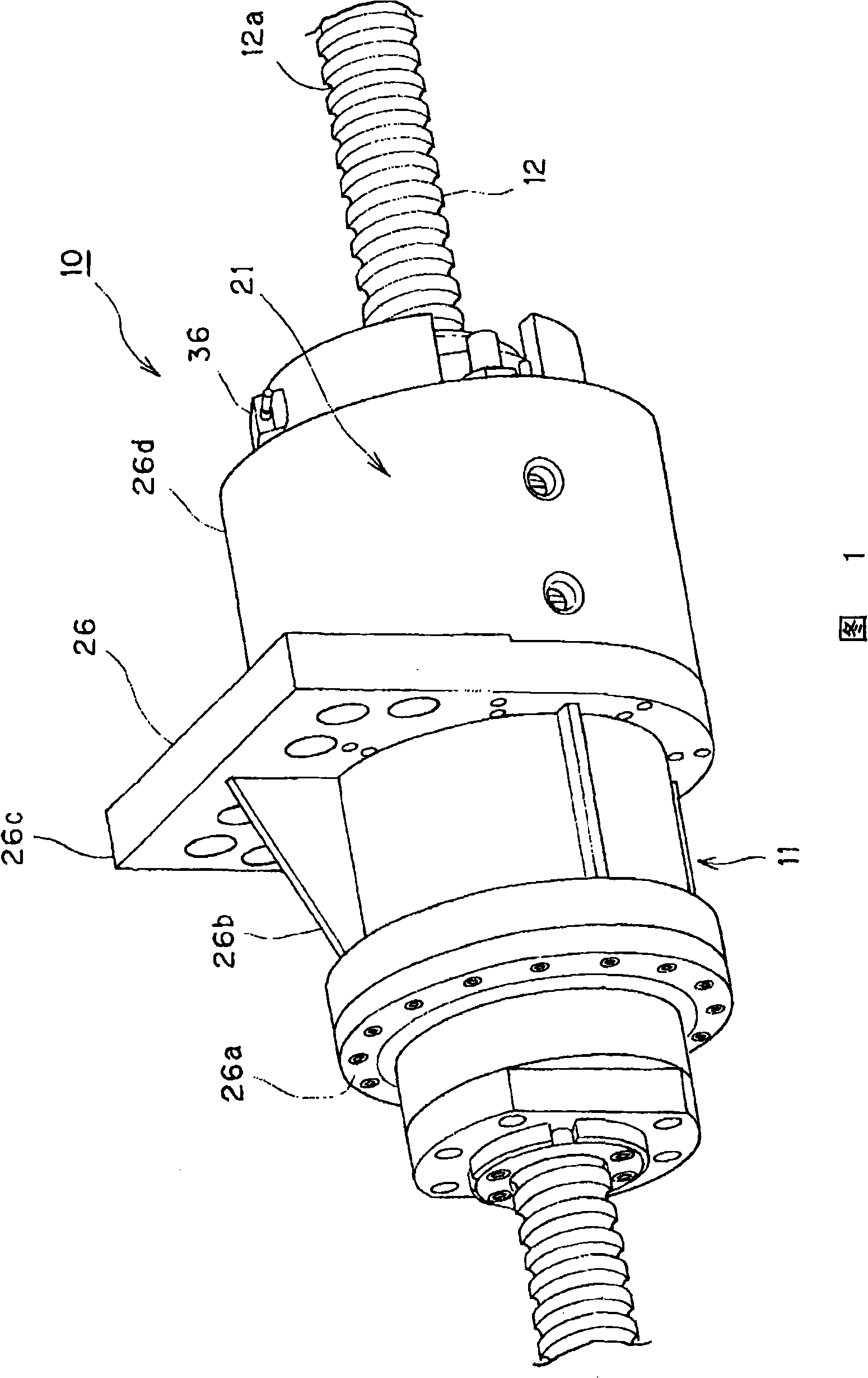
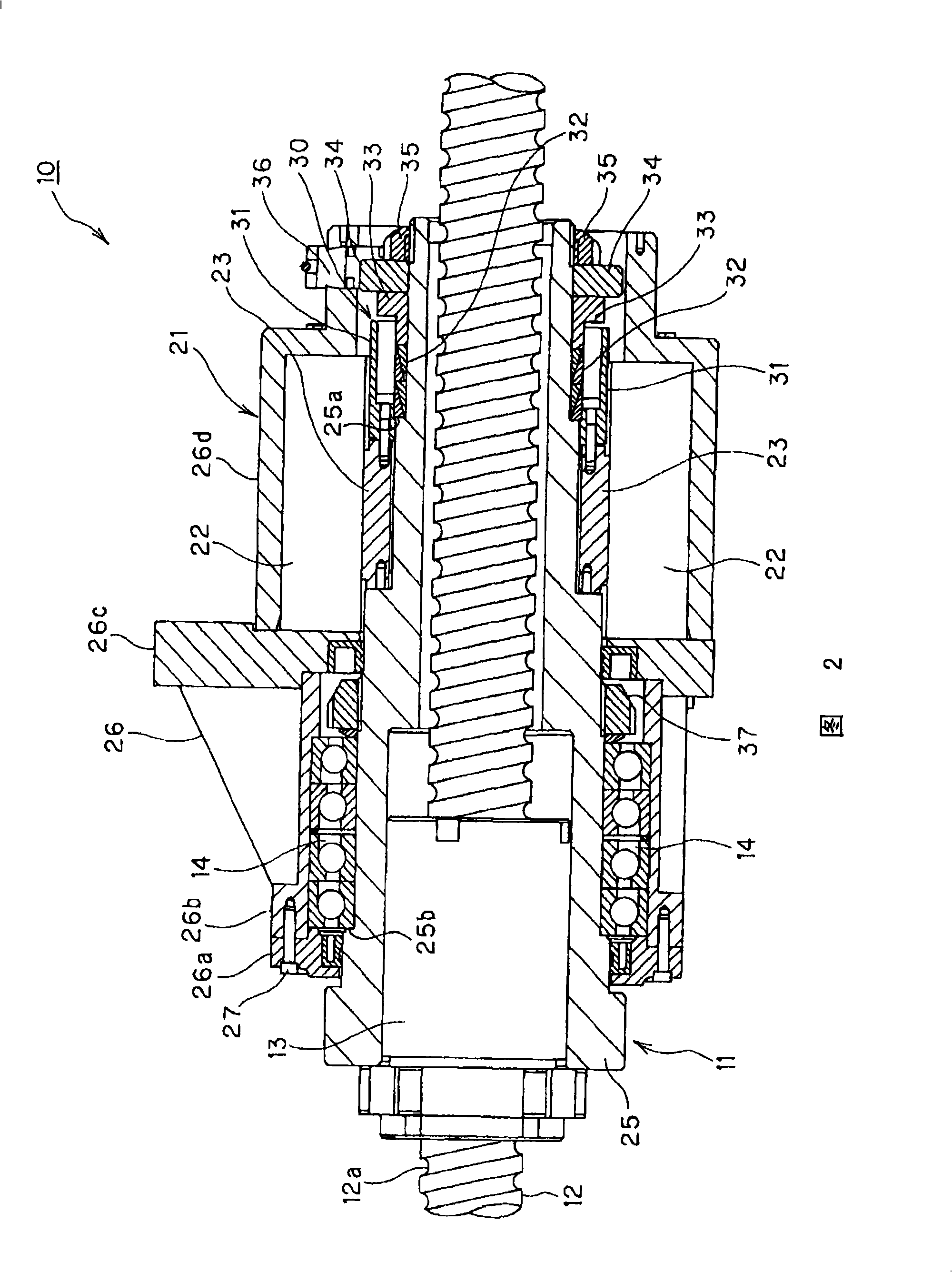
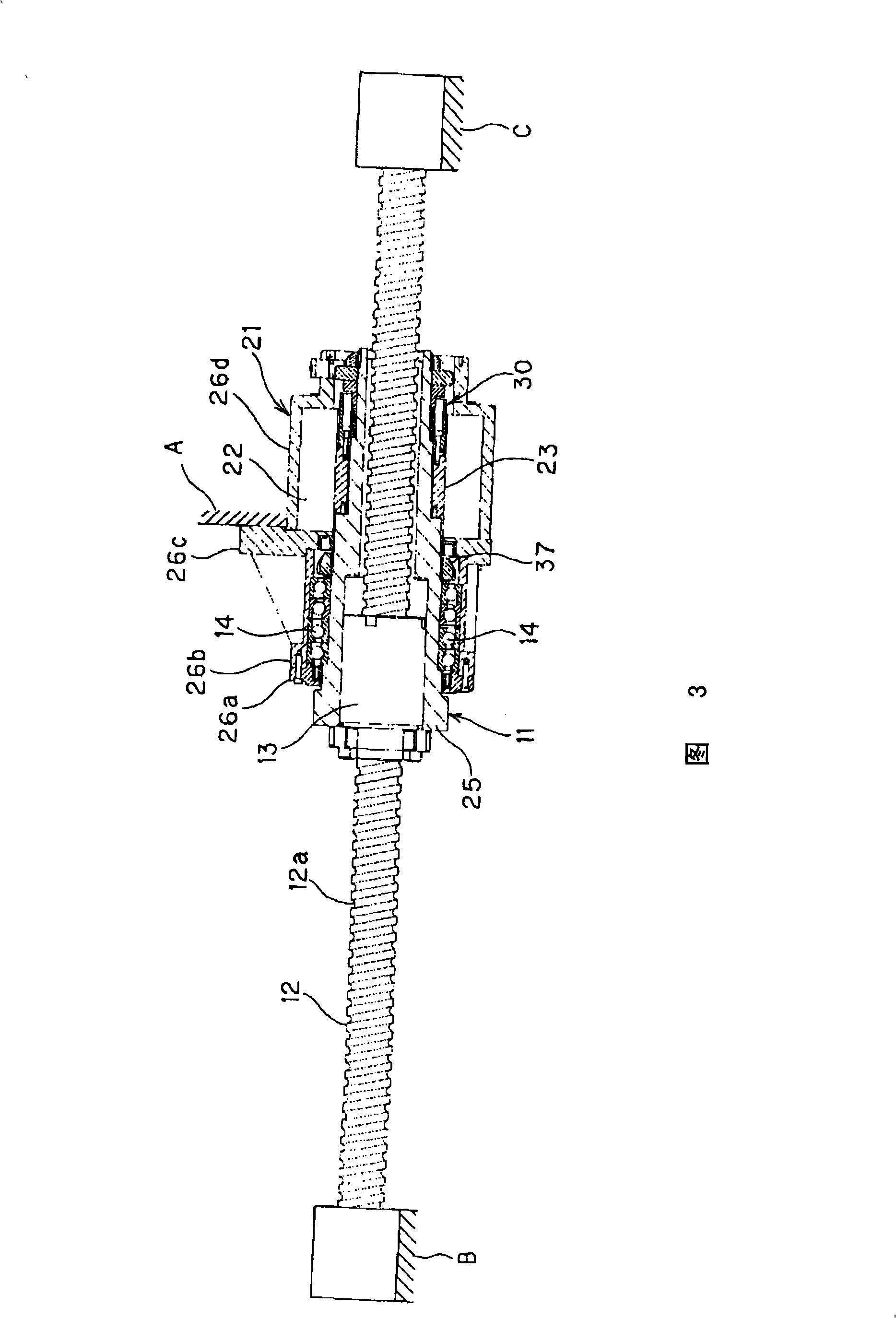
Hollow motor drive device

A motor-driven, hollow technology, applied in the direction of transmission, electromechanical devices, electric components, etc., can solve the problems of high rigidity, narrow application range, and large device shape, and achieve high rigidity, easy assembly and adjustment. Effect

Active Publication Date: 2008-12-31
THK CO LTD +1
View PDF2 Cites 13 Cited by
  • Summary
  • Abstract
  • Description
  • Claims
  • Application Information

AI Technical Summary

Problems solved by technology

[0007] However, in the driving device described in the above-mentioned Patent Document 2, since the hollow motor, the ball screw nut, and the spline mechanism are arranged in series, there is a problem that the rigidity is high, but the shape of the device has to be enlarged.
In particular, in this type of driving device, if the length of the device in the axial direction is increased, the installation space is limited, and the applicable range of the device is narrowed.

Method used


Image

  • Hollow motor drive device
  • Hollow motor drive device
  • Hollow motor drive device

Examples


Embodiment

[0081] A specific usage example of the hollow motor drive device 10 according to the above-mentioned embodiment will be described with reference to FIG. 4 . Fig. 4 is an external perspective view showing an example of use of the hollow motor drive device of this embodiment.

[0082] In the hollow motor driving device 10 of the present embodiment, the flange portion 26c among the members constituting the casing 26 is removed, and the rectangular block 40 is provided on the outer periphery of the casing 26 . In addition, two linear guides 45 are provided below the block 40, the moving block 45a among the parts constituting the linear guide 45 is connected to the block 40, and the track guide 45b among the parts constituting the linear guide 45 Connect to the abutment part as the setting standard.

[0083] Moreover, if the hollow motor part 21 is operated with the threaded shaft 12 fixed, only the block body 40 moves in the axial direction, and if the hollow motor part 21 is ope...


PUM


Abstract

A hollow motor drive device (10) comprises a screw shaft (12) with a spiral screw groove (12a) formed in the outer peripheral surface, a nut member (13) threaded with the screw groove (12a), a hollow drive shaft (25) with the nut member (13) fixedly fitted to its inner peripheral side and a permanent magnet (23) fitted to its outer peripheral side, and a housing (26) having a bearing part (14) rotatively supporting the hollow drive shaft (25) and a coil part (22). In the hollow drive shaft (25), the nut member (13) and the permanent magnet (23) are so disposed that they are not overlapped with each other in the direction perpendicular to the axial direction of the hollow drive shaft (25). In the housing (26), the bearing part (14) is disposed at a position corresponding to the nut member (13), and the coil part (22) is disposed at a position corresponding to the permanent magnet (23). By adopting this constitution, it is possible to provide a hollow motor drive device having a high rigidity, excellent stop-responsive performance, excellent maintainability and compact shape.

Description

technical field [0001] The present invention relates to a hollow motor driving device, which combines a screw / nut mechanism capable of transforming rotary motion and reciprocating linear motion with a hollow motor without a motor drive shaft. Background technique [0002] Conventionally, a drive device disclosed in, for example, Patent Document 1 below is known as a drive device that performs reciprocating linear motion in a uniaxial direction using a hollow motor. This driving device is a device in which a driven rod is arranged in a state penetrating through a hollow portion of a hollow motor, and the rotation of a cylindrical rotor forming the hollow portion is converted into a linear driving force of the driven rod and transmitted. Specifically, a female thread is cut on the inner peripheral surface of the rotor, a male thread capable of threading with the female thread is cut on the outer peripheral surface of the driven rod, and the driven rod is screwed into the inner...

Claims


Application Information

Patent Timeline
Patent Type & Authority Applications(China)
IPC IPC(8): H02K7/06F16H25/20
CPCF16H25/20F16H2025/2078H02K7/06
Inventor G·R·维尔勒D·洛伊克曼恩
Owner THK CO LTD
Learn More