Spray-gun flow regulator

A flow regulating device and flow regulating technology, applied in the direction of spraying devices, spraying devices, etc., can solve the problems of uneven discharge, uncontrollable flow, etc., achieve uniform discharge, simple structure, and improve work efficiency

Inactive Publication Date: 2009-01-07
NANJING HUAXIAN HIGH TECH CO LTD
View PDF0 Cites 10 Cited by
  • Summary
  • Abstract
  • Description
  • Claims
  • Application Information

AI Technical Summary

Problems solved by technology

[0003] The purpose of the present invention is to provide a spray gun flow adjustment device with simple structure and accurate adjustment for the problem that the existing spray gun device cannot control the flow rate and cause uneven discharge

Method used


Image

  • Spray-gun flow regulator

Examples


Embodiment Construction

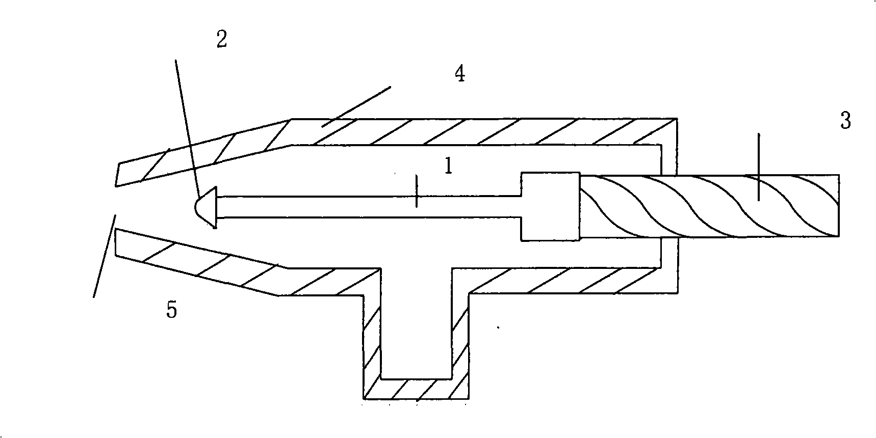
[0012] Attached below figure 1 And embodiment the present invention is described further.

[0013] A spray gun flow regulating device is characterized in that it includes a screw rod 1, a metal head 2, an adjustment knob 3 and a spray gun body 4, the metal head 2 is mounted on the front end of the screw rod 1, and the diameter of the metal head 2 is smaller than that of the spray gun mouth of the spray gun body 4 Diameter, adjusting knob 3 is contained in the rear end of screw rod 1, and the end that screw rod 1, metal head 2 and adjusting knob 3 are connected with screw rod 1 is all positioned at the inside of spray gun body 4, and the flow adjustment scale is marked on spray gun body 4.

[0014] When the present invention is used, the user rotates the adjusting knob 3 so that the screw rod 1 that controls the flow moves back and forth in the spray gun body 4. When the screw rod 1 drives the metal head, the outlet size of the spray gun mouth 5 will be changed due to the displ...


PUM


Abstract

A spray gun flow adjusting device is characterized in that the device comprises a screw (1), a metal head (2), an adjusting knob (3) and a spray gun body (4), wherein the metal head (2) is mounted at the front end of the screw (1); the adjusting knob (3) is mounted at the rear end of the screw (1); the screw (1), the metal head (2), and one end of the adjusting knob (3) which is connected with the screw (1) are positioned inside the spray gun body (4). The spray gun device has the advantages of convenient use, accurate quantification and high work efficiency.

Description

technical field [0001] The invention relates to a spray gun device, in particular to a spray gun flow regulating device which can precisely control the liquid flow. Background technique [0002] At present, in the manufacture of shadow mask type plasma displays, spray gun devices are usually used when spraying phosphor powder to the shadow mask, but the existing spray gun devices often spray the phosphor powder directly from the nozzle when the trigger of the spray gun is pulled. Its flow is often difficult to control, resulting in uneven discharge, unable to accurately spray a certain flow of phosphor spray according to specific needs, and unable to meet the needs of existing production technologies. Contents of the invention [0003] The object of the present invention is to provide a spray gun flow regulating device with simple structure and precise adjustment, aiming at the problem that the existing spray gun device cannot control the flow rate, resulting in uneven dis...

Claims


Application Information

Patent Timeline
Patent Type & Authority Applications(China)
IPC IPC(8): B05B1/32
Inventor 林豪朱立锋林青园
Owner NANJING HUAXIAN HIGH TECH CO LTD
Why Eureka
Try Eureka