
Resonance type optical gyroscope signal checking method

An optical gyroscope and signal detection technology, which is applied in the direction of speed measurement by gyroscope effect, rotating gyroscope, Sagnac effect gyroscope, etc., can solve the problem of not being able to respond quickly to changes in angular velocity, and achieve the effect of improving accuracy

Inactive Publication Date: 2009-01-07
BEIHANG UNIV
View PDF0 Cites 13 Cited by
  • Summary
  • Abstract
  • Description
  • Claims
  • Application Information

AI Technical Summary

Problems solved by technology

The frequency locking process always requires a certain response time, which makes the gyroscope always in the process of continuous frequency locking when it is working, and cannot quickly respond to changes in angular velocity and give output values ​​​​in time.

Method used


Image

  • Resonance type optical gyroscope signal checking method
  • Resonance type optical gyroscope signal checking method
  • Resonance type optical gyroscope signal checking method

Examples


Embodiment Construction

[0031] The technical solution of the present invention will be further described below in conjunction with the embodiments.

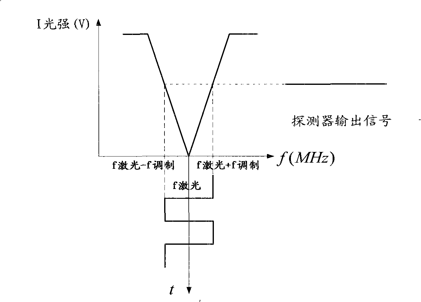
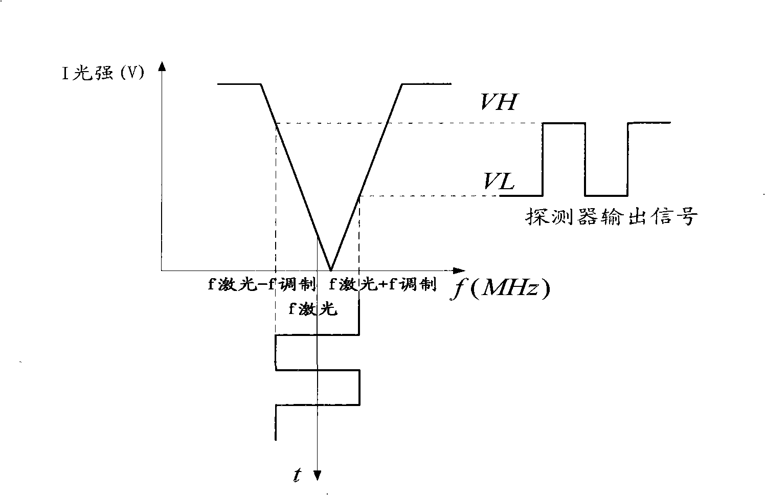
[0032] The technical scheme of the invention proposes a method of using the demodulation value of the gyroscope detection signal for common-mode frequency locking and differential mode detection, so that the response time of the gyroscope is greatly shortened and noise is suppressed.

[0033] like image 3 Shown, the schematic diagram of the signal detection method of a kind of resonant optical gyroscope of the present invention;

[0034] When the gyroscope is working, the clockwise and counterclockwise two lights are respectively f1 and f2, and their corresponding light intensity demodulation values ​​on the demodulation curve are I1 and I2, so the common mode value I1+I2 of the demodulation value can be calculated The value of the center frequency of the light source offset is obtained, and the frequency difference f2-f1 of the two paths of light can...


PUM


Abstract

The invention discloses a detection method for resonant optical gyro signals, which comprises: modulating the light frequency of the light emitted by the light source both in the clockwise direction and the counterclockwise direction when the gyro works; demodulating a curve by a modulation method; demodulating the corresponding light intensity values of the frequencies of the two-path light on the curve; deriving a common modulus and a difference modulus based on the light intensity values; demodulating light source frequency offset based on the common modulus; returning the light source frequency offset to the light source; locking the two-path light frequencies by regulating the output frequency of the light source; demodulating the frequency difference of the two-path light based on the difference modulus; detecting the rotating angular velocity of the gyro. The method of the invention can effectively increase the corresponding speed of gyro output, measure the rotating angular velocity of the gyro in time and reduce noise.

Description

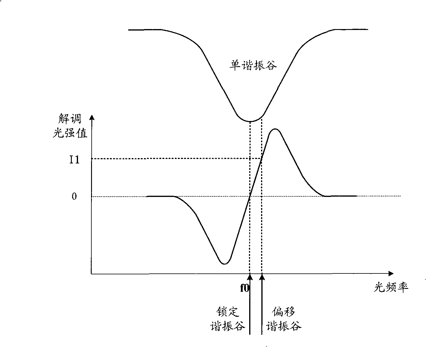
technical field [0001] The invention relates to the technical field of inertial rotation sensors, in particular to a resonant optical gyroscope signal detection method. Background technique [0002] Resonator optic gyro is an inertial angular velocity sensor that utilizes the Sagnac effect to detect rotational angular velocity. [0003] At present, the resonant optical gyro signal detection method in the prior art adopts a single-channel frequency-locked signal detection. After the clockwise and counterclockwise two-way light output by the light source is modulated by a frequency shifter, each becomes a beam of light whose optical frequency oscillates according to the modulation period. , according to the demodulated data of the modulated light, the value of the deviation of the optical frequency from the center of the resonance valley can be calculated (the relationship between the optical frequency and the demodulated data is as follows figure 1 shown). [0004] When the...

Claims


Application Information

Patent Timeline
Patent Type & Authority Applications(China)
IPC IPC(8): G01C19/72G01P9/02G01C19/02
Inventor 马迎建姜楠洪灵菲冯丽爽于怀勇刘惠兰
Owner BEIHANG UNIV
Learn More