Appearance inspecting device for substrate

A technology for an appearance inspection device and a substrate, which is applied to measurement devices, image detector methods, image signal processing, instruments, etc., can solve problems such as difficulty in saving space in manufacturing equipment, inability to shorten production takt time, etc. Takt time, miniaturization, and the effect of reducing setup space

Inactive Publication Date: 2009-01-07
OLYMPUS CORP
View PDF1 Cites 32 Cited by
  • Summary
  • Abstract
  • Description
  • Claims
  • Application Information

AI Technical Summary

Problems solved by technology

[0004] However, in the above-mentioned Patent Document 1, in the LCD manufacturing process, in the case of performing the visual inspection by the camera on the glass substrate conveyed on the production line, it is necessary to temporarily take out the glass substrate from the production line for inspection, and there is a problem that the production cannot be shortened. takt time problem
Furthermore, when the visual inspection device is arranged independently of the production line, it requires a space for its arrangement and a mechanism such as a transport robot, and there is also a problem that it is difficult to save space in manufacturing equipment.

Method used


Image

  • Appearance inspecting device for substrate
  • Appearance inspecting device for substrate
  • Appearance inspecting device for substrate

Examples


no. 1 Embodiment approach

[0040] Next, a substrate appearance inspection device according to a first embodiment of the present invention will be described with reference to the drawings.

[0041] The substrate appearance inspection device 1 of the present embodiment is mainly installed in a substrate production line and used to inspect the surface of a substrate conveyed by a conveyor or the like.

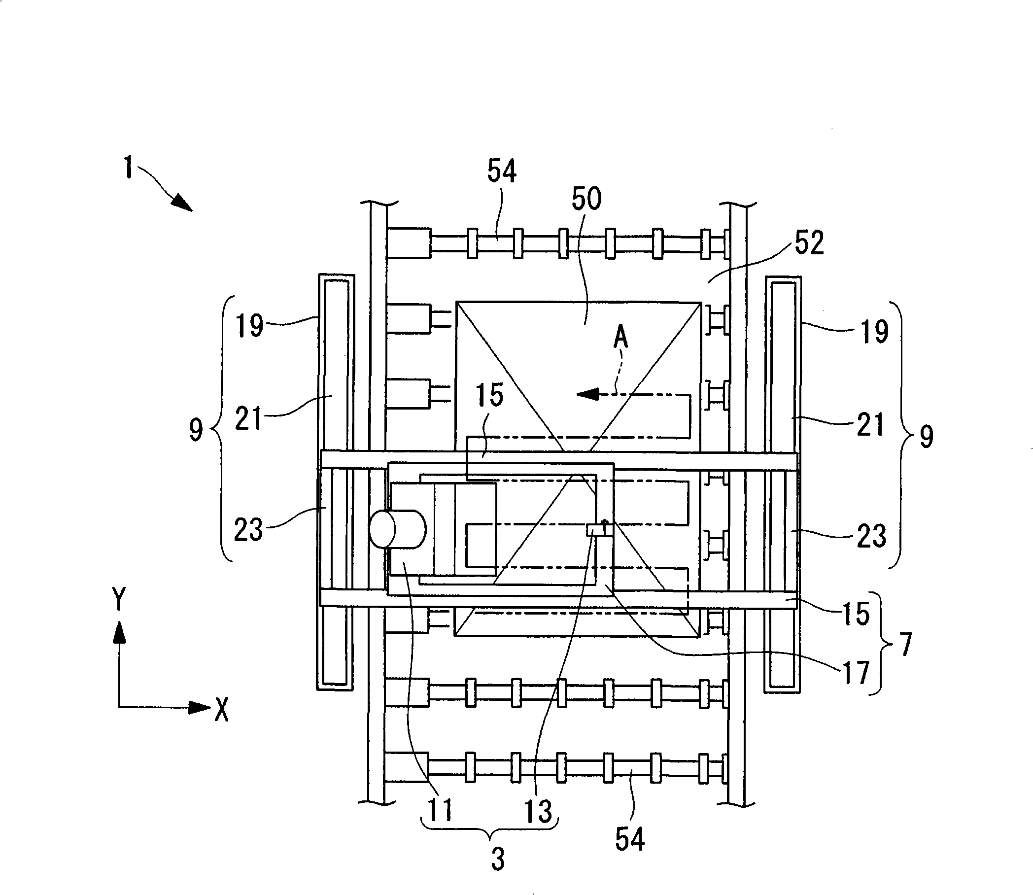
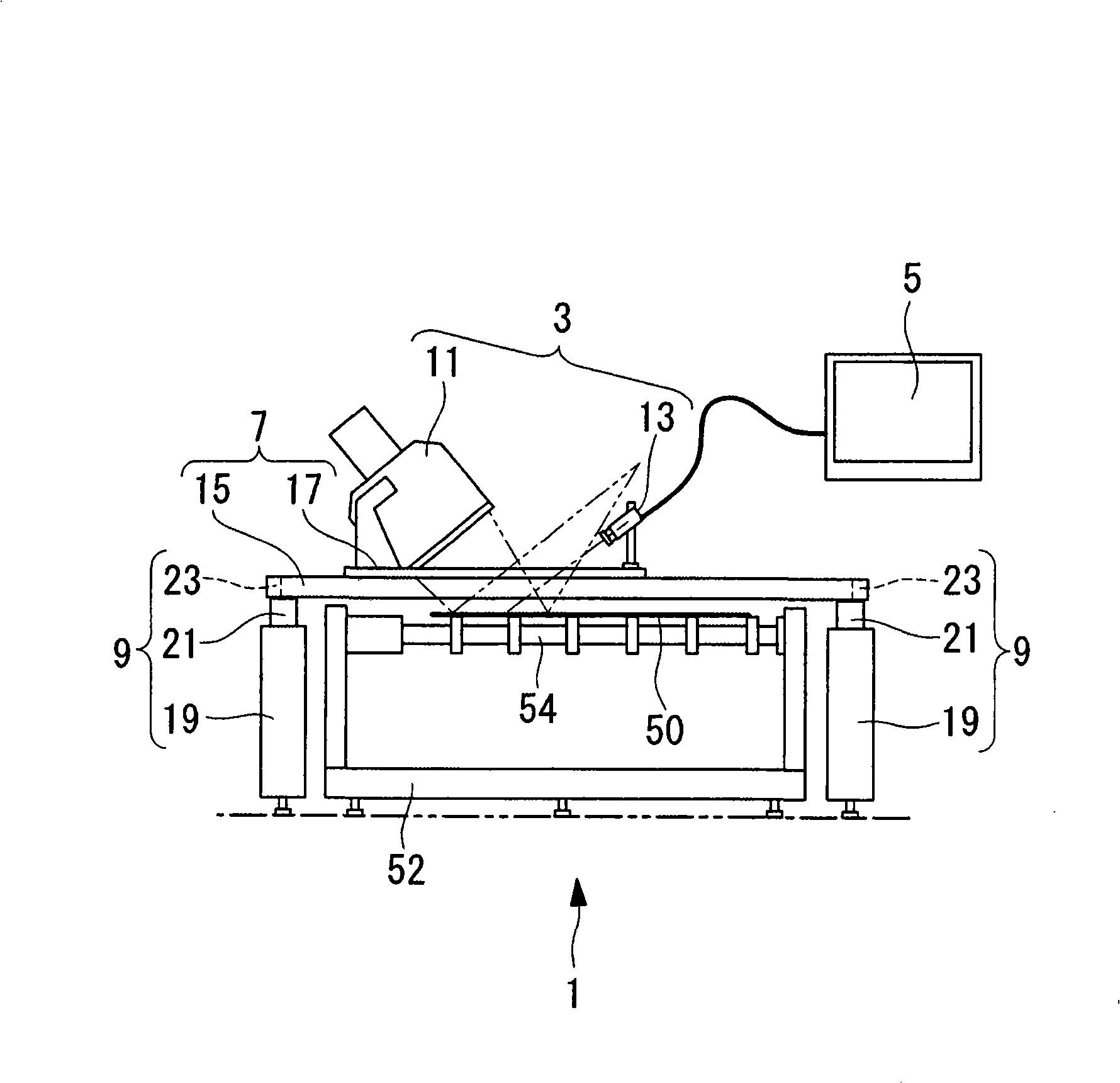
[0042] Such as figure 1 with figure 2As shown, the substrate appearance inspection device 1 has: an inspection device unit 3, which observes the appearance of the surface of the substrate 50 conveyed on the production line 52; a monitor 5, which displays an image taken by the inspection device unit 3; a moving mechanism 7 that moves the inspection device unit 3 in a direction intersecting the substrate 50 conveyance direction; and a second movement mechanism 9 that moves the inspection device unit 3 in the substrate 50 conveyance direction.

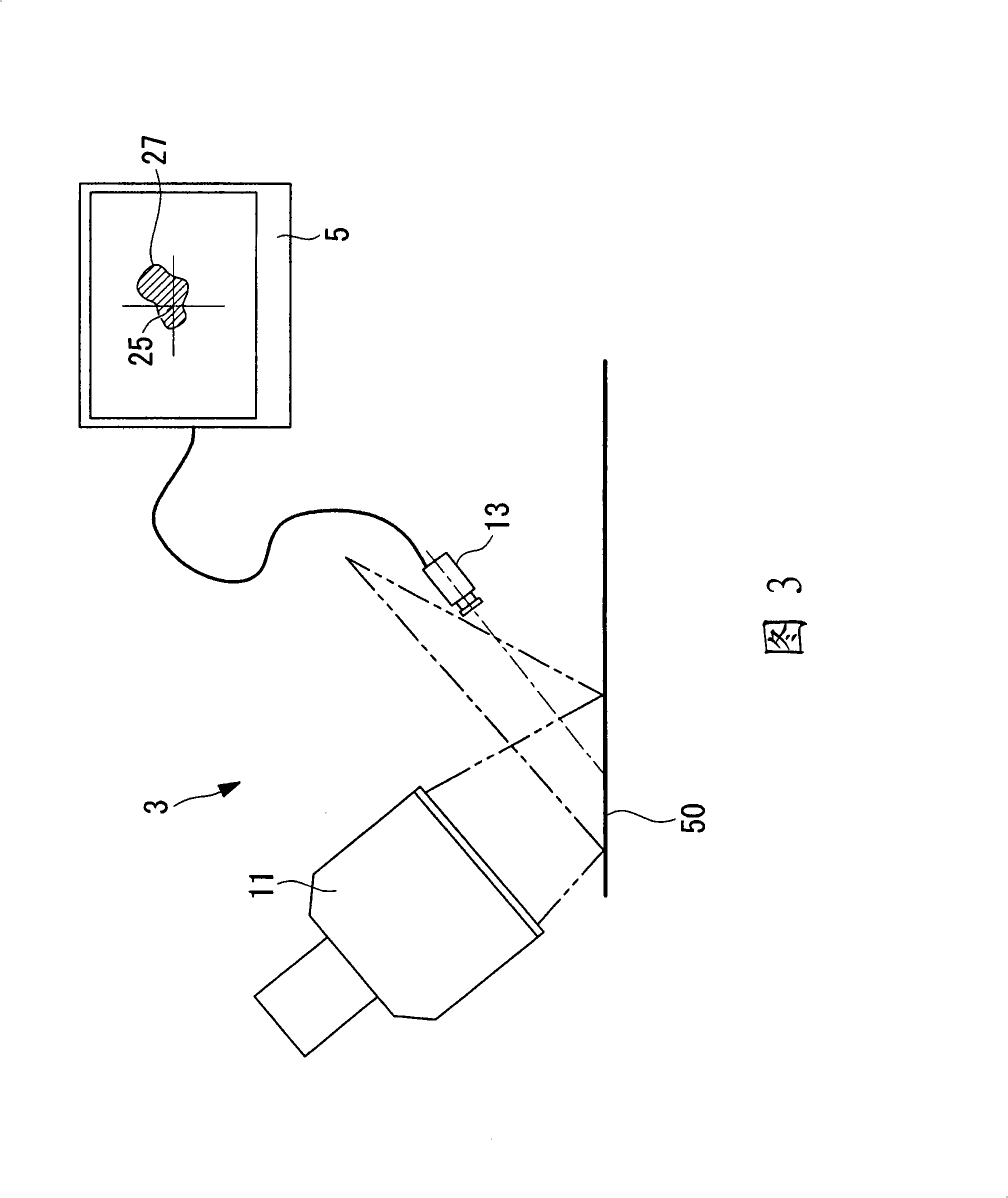
[0043] As shown in FIG. 3 , the inspection device unit 3 has:...

no. 2 Embodiment approach

[0080] Next, refer to Figure 5 with Image 6 A substrate appearance inspection device 31 according to a second embodiment of the present invention will be described.

[0081] The inspection device unit 3 of the substrate appearance inspection device 31 of the present embodiment has a guide (rotation mechanism) 33 .

[0082] Hereinafter, the same reference numerals are assigned to the same parts as those of the substrate appearance inspection apparatus 1 according to the first embodiment, and description thereof will be omitted.

[0083] The guide 33 rotates the camera 13 so that the optical axis of the camera 13 always faces the center position 35 of the irradiation range of the illumination light irradiated from the illumination device 11 on the substrate 50 . Specifically, the guide 33 is a semicircular guide rail, and the camera 13 is installed so as to be movable along the guide 33 .

[0084] Furthermore, the guide 33 is installed at an angle of about 45° relative to th...


PUM


Abstract

The invention provides a substrate appearance inspection device. detailed appearance inspection of whole surface can be carried out without taking out glass substrate on the product line, accordingly production period is shorten and manufacture equipment is miniaturized. The substrate appearance inspection device (1) has an illumination device (11) generating illumination light for irradiation on surface of substrate (50) on the product line (52); a camera (13) picking-up image of surface of the substrate (50) illuminated by the illumination device (11); and a moving mechanism integrally moving the illumination device (11) and camera (13) in crossed direction of transmission direction of the substrate (50) on the product line (52), the camera (13) is collocated outside of range of light beam of specular reflection light by the substrate (50) surface from the illumination light of the illumination device (11).

Description

technical field [0001] The invention relates to a substrate appearance inspection device. Background technique [0002] Conventionally, there is known a substrate appearance inspection device that visually observes defects or the like generated on a glass substrate when manufacturing FPDs (flat panel displays) such as LCDs (liquid crystal displays). In this way, inspection based on visual inspection is generally also called macroscopic observation. By irradiating a surface light source based on a macroscopic observation unit to the surface of the substrate to be inspected supported on the holder, and using a television camera to capture the reflected light on the surface of the substrate to be inspected changes, so as to perform visual inspection based on macroscopic observation (for example, refer to Patent Document 1 Image 6 ). [0003] [Patent Document 1] Japanese Patent Application Laid-Open No. 10-111253 [0004] However, in the above-mentioned Patent Document 1, in ...

Claims


Application Information

Patent Timeline
Patent Type & Authority Applications(China)
IPC IPC(8): G01N21/896G02F1/13
CPCG01N21/8806G01N2021/177G01N2021/9513G02F1/1303
Inventor 冈平裕幸
Owner OLYMPUS CORP
Why Eureka
Try Eureka