Projection exposure device and method and device for calibrating illumination light beam dynamic positional error

A lighting beam and dynamic position technology, applied in the field of lithography, can solve the problems of high cost, insignificant effect, and inaccurate displacement correction, and achieve the effect of obvious correction effect, low cost, and elimination of dynamic position error

Active Publication Date: 2009-01-07
SHANGHAI MICRO ELECTRONICS EQUIP (GRP) CO LTD
View PDF4 Cites 10 Cited by
  • Summary
  • Abstract
  • Description
  • Claims
  • Application Information

AI Technical Summary

Problems solved by technology

Due to the fact that the mechanical vibration of the lighting system may not accurately reflect the positional deviation of the actual lighting beam, etc., the displacement has not been ac

Method used


Image

  • Projection exposure device and method and device for calibrating illumination light beam dynamic positional error
  • Projection exposure device and method and device for calibrating illumination light beam dynamic positional error
  • Projection exposure device and method and device for calibrating illumination light beam dynamic positional error

Examples


no. 1 example

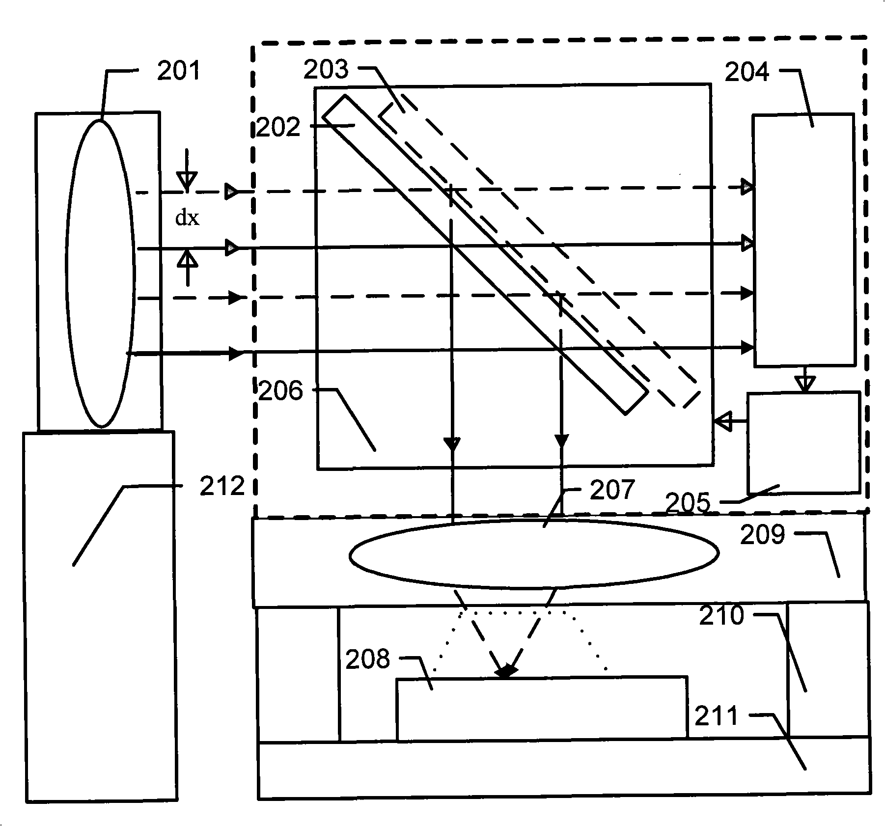
[0028] like figure 2The device for dynamically correcting the dynamic position error of the illumination light beam in this embodiment is shown in the dotted box in the figure, and includes a movable mirror 202, which is a beam splitter with 1% light transmission and 99% light reflection, with an angle of 45 degrees Obliquely placed at the pupil of the lighting mirror group, an image sensor (CCD) or position sensitive sensor (PSD) 204 is used to collect and measure the position of the beam center at the pupil of the lighting mirror group, and a control device 205 can The position of the movable lens 202 is controlled in real time by a motor, and a movable lens frame 206 is used to place and drive the movable lens 202 to translate. It should be noted that, in view of the influence of the dynamic position error in the scanning direction of the illumination beam on the dose performance in scanning exposure is much greater than the impact of the dynamic position error in the non-...

no. 2 example

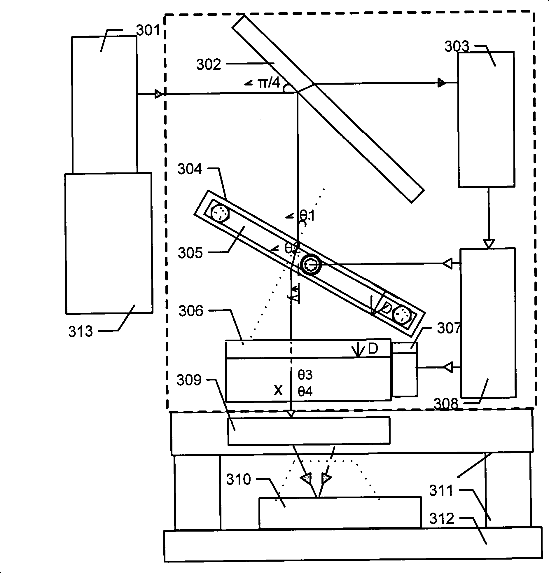
[0034] see image 3 , as shown in the dashed box, the device for dynamically correcting the displacement of the illumination beam relative to the objective lens in this embodiment includes a movable lens group, a pupil position measuring device 303 , and a control device 308 .

[0035] The movable lens group includes a 45-degree oblique 99% reflective and 1% transmissive fixed beamsplitter 302 placed at the pupil of the illuminating mirror group for reflecting and refracting the illuminating beam; The movable refractor 304 whose direction forms an angle of θ1, whose thickness is D, and whose refractive index is n can rotate with the rotating device 305 on the non-scanning direction as the axis, and is used to refract light in the scanning direction and correct the beam position error in the scanning direction, here , the refraction angle is θ2, and the light beam causes a position shift y in the scanning direction; in addition, it also includes a movable refractor 306 with an ...


PUM


Abstract

The invention provides a projection and exposure device and a device for correcting the dynamic location error of an illuminating beam and a method thereof, wherein, the projection and exposure device structure separates a lighting system from the pupil position of an illuminating mirror group and arranges an optical element behind the pupil of the illuminating mirror group on a main frame on which a reticle stage is also arranged, meanwhile, the optical element in front of the pupil of the illuminating mirror group is arranged on a mechanical frame on which the lighting system is also arranged, thus transforming the displacement error of light luminous into a small telecentric angle error; and the device and the method for correcting the dynamic location error of the illuminating beam of a photoetching machine further reduces the telecentric angle error. By adopting the invention, the smaller displacement of the light luminous corresponding to an objective is transformed into the slight change of a pupil telecentric degree or a lighting telecentric angle, and by utilizing the advantage that the slight change of the lighting telecentric angle has little influence on each property of the photoetching machine, scan dose performance is improved.

Description

technical field [0001] The invention belongs to the field of photolithography, and relates to a structure of a projection exposure device, and a device and method for correcting a dynamic displacement error of an illumination beam relative to an objective lens. Background technique [0002] In a scanning lithography machine, due to various factors such as illumination frame and variable slit vibration, the position of the illumination beam relative to the objective lens changes with time during exposure. This position change is called the dynamic position error of the illumination beam. For example, when the illumination frame where the exit of the illumination system is located and the main frame where the objective lens is located are separated above the mask table, the position of the illumination beam changes dynamically with the mutual vibration of the two frames, and the range of change is relatively large (for example, about 50-500 microns ), the frequency is low (suc...

Claims


Application Information

Patent Timeline
IPC IPC(8): G03F7/20G02B27/00
Inventor 张俊
Owner SHANGHAI MICRO ELECTRONICS EQUIP (GRP) CO LTD
Why Eureka
Try Eureka