Flexible transmission tubular wire twisting machine

A flexible transmission and stranding machine technology, applied in the manufacture of electrical components, circuits, cables/conductors, etc., can solve the problems such as the decline of the accuracy of the whole machine and the performance of the equipment, the quality of the cable products, and the short service life of the equipment. The effect of slow machine accuracy and equipment performance, reduced coaxiality requirements, and long equipment life

Inactive Publication Date: 2009-01-07
德阳东佳港智能装备制造股份有限公司
View PDF0 Cites 5 Cited by
  • Summary
  • Abstract
  • Description
  • Claims
  • Application Information

AI Technical Summary

Problems solved by technology

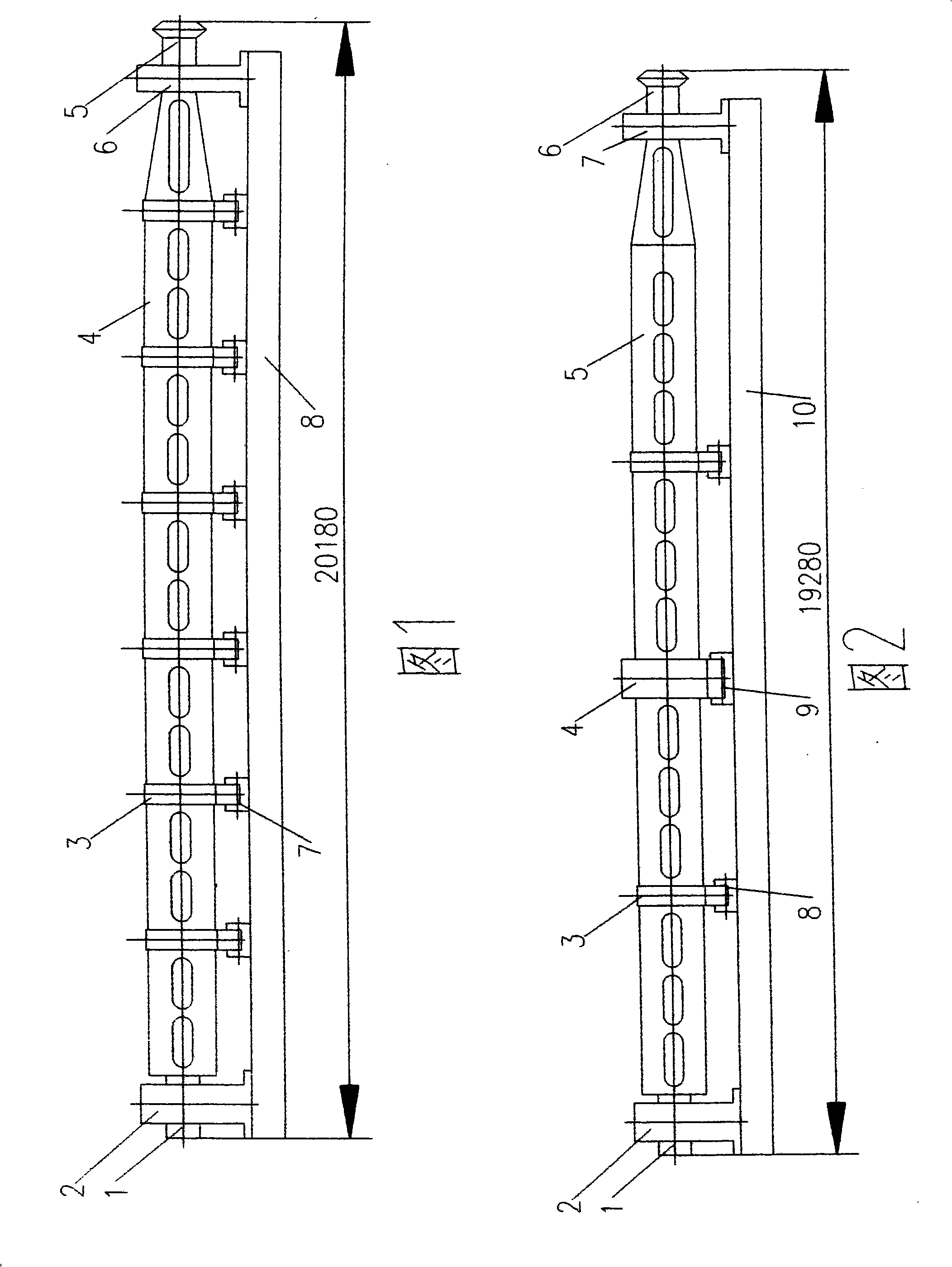
[0003] 1. The total length of the rotating strand is 19.28m. It is composed of a gearbox end bearing seat 2, left and right support shafts (1, 5), six-section cylinder 4 and a tail end bearing seat 6, a total of ten parts. There are too many permanent support points, forming over-positioning support, and all of them are assembled by rigid connection. Since the relative position accuracy of each support point after assembly is difficult to guarantee, the coaxiality is low, and the deflection of the rotating twisted body is large, the design of the stranding machine allows The rated speed is low and the production efficiency is low
[0004] 2. In order to improve the coaxiality of the ten parts of the rotating stranded body after assembly, the precision of these parts has to

Method used


Image

  • Flexible transmission tubular wire twisting machine
  • Flexible transmission tubular wire twisting machine

Examples


Embodiment Construction

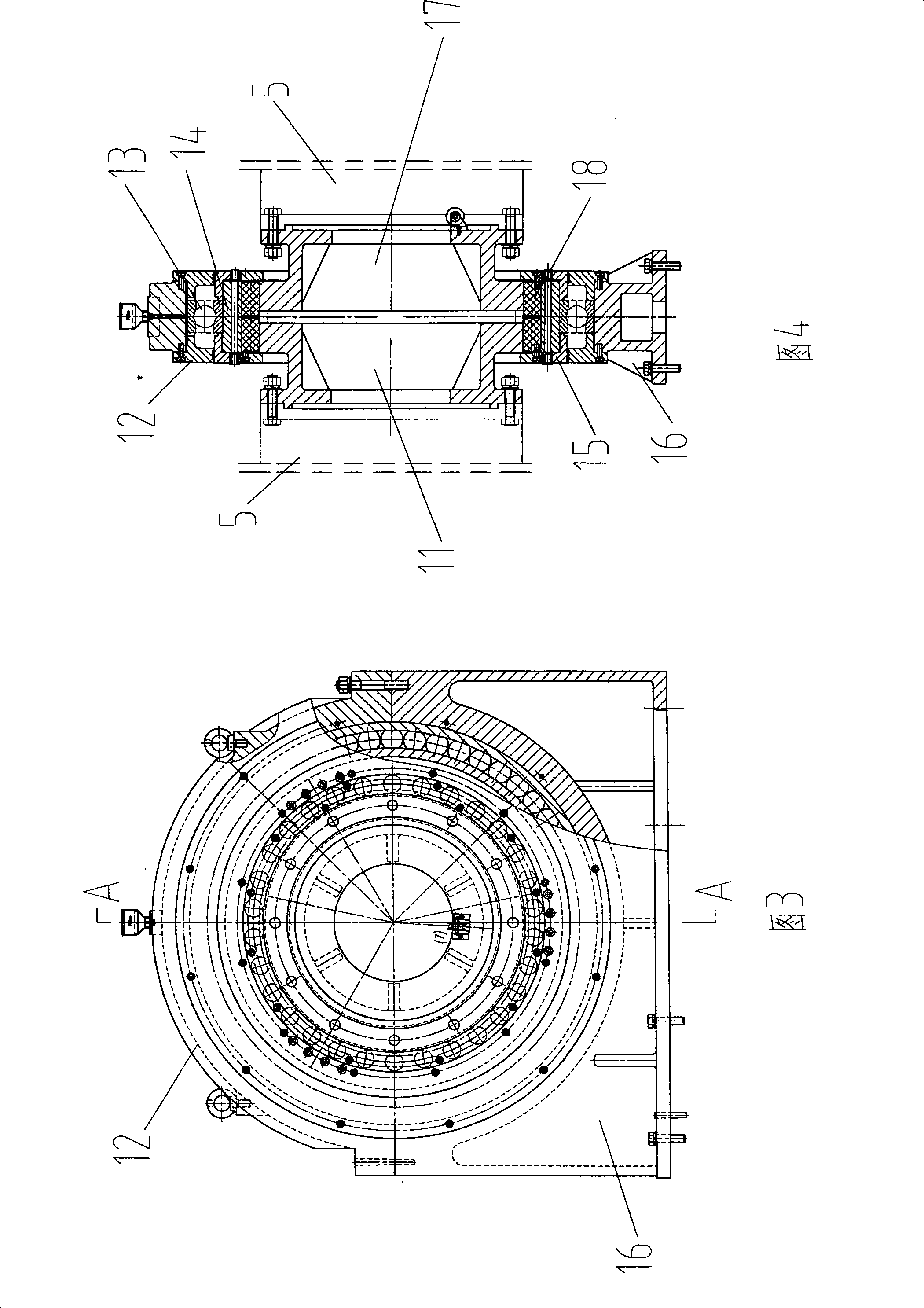
[0025] See Fig. 2: The main part of the tubular stranding machine is a rotating strand, which is composed of a cylinder body 5, a gearbox end bearing seat 2, a tail end bearing seat 7, a supporting roller 8, and a base 10. The bearing seat 2 at the gearbox end and the bearing seat 7 at the tail end are arranged at the two ends of the base 10, corresponding to each other; the two ends of the cylinder 5 have supporting shafts 1 and 6 respectively, which are supported on the bearing seat 2 at the gearbox end and the bearing seat at the tail end 7; the waist of the cylinder 5 has a plurality of supporting roller tracks 3 distributed axially; the supporting rollers 8 are arranged on the base 10, the number of which is the same as that of the supporting roller tracks 3, and each supporting roller 8 supports one supporting roller runway 3.

[0026] Because the length of the barrel 5 is very long, at least more than 10 meters, the total length of the barrel 5 is close to 20 meters for...


PUM


Abstract

The invention discloses a flexible driving tube stranding machine which comprises a rotating stranding body, a gear box end bearing pedestal, a tail end bearing pedestal, support riding wheels and a base; the gear box end bearing pedestal and the tail end bearing pedestal are arranged at the two ends of the base and oppositely correspond to each other; the two ends of the rotating stranding body are respectively provided with a supporting axle; the supporting axles are supported on the gear box end bearing pedestal and the tail end bearing pedestal; the waist part of the rotating stranding body is provided with a plurality of riding wheel runways axially distributed; the support riding wheels are arranged on the base and have the same number as the riding wheel runways; each support riding wheel correspondingly supports a riding wheel runway; the rotating stranding body is formed by connecting a plurality of tube sections; a connection point is arranged between every two adjacent tube sections, and at least one connection point is connected by using a flexible pin coupling; the coupling is provided with a bearing and a bearing pedestal; the bearing pedestal is supported on the base, and the bearing is a deep groove ball bearing. Compared with the existing tube stranding machine, the flexible driving tube stranding machine can further improve the technical performance of the stranding machine and improve the rotation speed and the production efficiency under the preconditions of simplifying the structure, reducing the precisions of processing, assembly, installation, debugging and maintenance.

Description

technical field [0001] The invention relates to wire and cable processing equipment, in particular to a tubular stranding machine. Background technique [0002] In the wire and cable manufacturing process, it is necessary to use a twisting machine to twist the single wires and strands before they can be made into finished cables. Existing stranding machines are usually tubular stranding machines, which are assembled on a rigid base by gear box end bearing housings, rotating strands, supporting rollers, tail end bearing housings and other components to form the main machine (see Figure 1). The length of the stranding machine host is very long. Take the JG500 / 12 tubular stranding machine as an example, the total length of the host is as long as 20.18m, and the main component of the stranding machine is a circular tubular rotary body with a length of 19.28m. Restricted by processing and transportation conditions, the cylinder body 4 of the rotating twisted body is processed in...

Claims


Application Information

Patent Timeline
IPC IPC(8): H01B13/02
Inventor 许健庄家陈隆森
Owner 德阳东佳港智能装备制造股份有限公司
Why Eureka
Try Eureka