Transmission device and drive unit having transmission device

A transmission device and drive unit technology, applied to transmission devices, gear transmission devices, transmission device parts, etc., can solve problems such as noise, wear, and ball bearings that are not suitable for large axial forces

Active Publication Date: 2018-08-03
SCHAEFFLER TECH AG & CO KG
View PDF8 Cites 0 Cited by
  • Summary
  • Abstract
  • Description
  • Claims
  • Application Information

AI Technical Summary

Problems solved by technology

However, this larger gap leads to relative movements in the connection precisely in the case of connections where there is an undesired misalignment
These relative movements may cause noise and may also cause undesired wear
[0005] In addition, the axial clamping force in this arrangement may lead to axial f

Method used


Image

  • Transmission device and drive unit having transmission device
  • Transmission device and drive unit having transmission device

Examples


Embodiment Construction

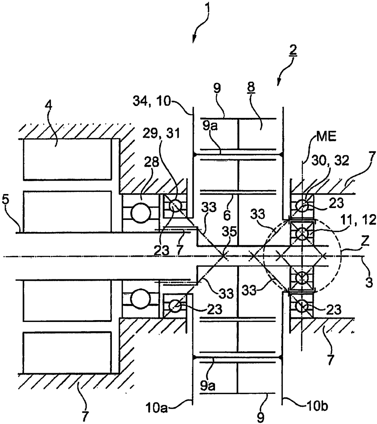
[0031] figure 1 : The drive unit 1 has an electric motor drive 4, the rotor shaft 5 of which is operatively connected to the sun gear 6 of the transmission 2 via a form-fit connection. The form-locking connection is produced, for example, by means of splines, so that the sun gear 6 can be displaced axially in a limited manner relative to the rotor shaft 5 . This ensures that no axial force of the sun gear 6 can be applied to the bearing 28 of the rotor shaft 5 . The transmission 2 is not shown completely. Parts of the housing 7 and the planetary gear 8 can be seen. The planetary transmission 8 is composed at least of a planet carrier 10 , a sun gear 6 and a set of planet gears 9 . The planet carrier 10 has two carrier plates 10 a and 10 b on which the planet pins 9 a are carried. The planet wheels 9 are seated on the planet pins 9a. The axes of rotation of the sun gear 6 and of the planet carrier 10 are each the central axis 3 . The sun gear 6 is axially supported or sup...


PUM


Abstract

The invention relates to a transmission device (2), at least comprising a housing (7) and a planetary gearing (8), wherein the planetary gearing (8) is formed at least of a planet carrier (10) mountedin the housing (7) for rotation about a central axis (3) of the transmission device (2) and a sun gear (6), which can be rotated about the axially oriented central axis (3) and which is in tooth engagement with planet gears (9), and wherein the sun gear (6) is axially supported against a component (34) of the transmission device (2) in the direction of the central axis (3) by means of an axial bearing (11).

Description

technical field [0001] A transmission with at least one housing and a planetary transmission, wherein the planetary transmission consists at least of a planet carrier rotatably mounted in the housing about a central axis of the transmission and a planetary carrier rotatable about an axial central axis 1. The sun gear is in a tooth engagement state with the planetary gear, and wherein the sun gear is axially supported on the components of the transmission device in the same direction as the central axis by means of an axial bearing. The invention also relates to a drive unit with an electric drive and such a transmission, in which the sun gear is connected to the rotor shaft of the electric drive. Background technique [0002] Such a transmission is disclosed in JP2011208758A2. The transmission is a hybrid drive train with a combustion engine and two electric motors. The electric motor can optionally be used as a drive or as a generator. The rotor shaft of one of the drive...

Claims


Application Information

Patent Timeline
IPC IPC(8): F16H57/08F16H1/28
CPCF16C19/16F16C19/166F16C19/545F16C35/06F16C2361/61F16H1/2845F16H57/08
Inventor 托斯滕·比尔曼菲利普·武尔茨贝格尔
Owner SCHAEFFLER TECH AG & CO KG
Why Eureka
Try Eureka