Sowing plough

A technology for sowing furrows and seeders, which is applied in the direction of sowing, plows, shovels, etc., and can solve the problem of reducing the distance between sowing grooves

Inactive Publication Date: 2009-01-07
JANG JADONGHWA
View PDF0 Cites 2 Cited by
  • Summary
  • Abstract
  • Description
  • Claims
  • Application Information

AI Technical Summary

Problems solved by technology

However, due to the ridges formed on the sides of the seeding grooves,

Method used


Image

  • Sowing plough
  • Sowing plough
  • Sowing plough

Examples


Embodiment Construction

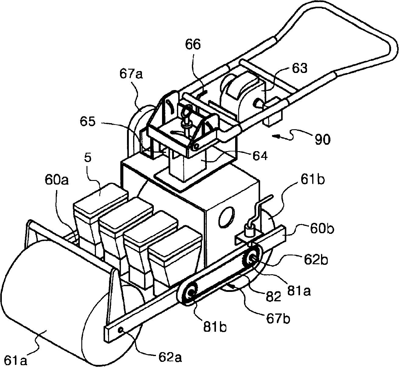
[0038] [35] cf. image 3 , the planter provided with the first roller 61a and the second roller 61b at the front and rear uses the engine 63 (or a driving motor powered by a battery) to generate driving force. Such as Figure 4 As shown, in order to rotate the drive shaft 52 of the hopper mounting unit, the driving force of the engine 63 is transmitted through the engine transmission unit 90 by means of the speed reducer 64, the first clutch 65 for selectively transmitting the rotational driving force and The power transmission device 67a rotates one of the first roller shaft 62a and the second roller shaft 62b, and is connected to the first drive gear 81a and the second roller shaft 62b mounted on the first roller shaft 62a and the second roller shaft 62b, respectively. On one of the two driving gears 81b, the first roller shaft 62a and the second roller shaft 62b are rotated by the first transmission chain 82 connecting them.

[0039] [36] If power transmission can be acco...


PUM


Abstract

A sowing machine of a unitary structure includes an engine driving unit for rotating a drive shaft of a hopper mounting unit connected with a first or second roller shaft which is rotated manually or by an actuation of an engine of the sowing machine, wherein the drive shaft of the hopper mounting unit is connected to the first or second roller shaft to perform a rotational movement to regularly discharge a preset amount of seeds or the hopper mounting unit has a driving unit for regularly discharging a preset amount of seeds; a hopper detachably mounted to a top of the hopper mounting unit to contain seeds; a shovel provided in a bottom of the hopper mounting unit to form a sowing groove; a guide plate for guiding the seeds discharged from the hopper to the sowing groove; and a molding unit. The sowing machine can be easily operated by anybody, and the hopper can discharge seeds along with the forward movement of the sowing machine, thereby ensuring correct sowing intervals.

Description

technical field [0001] [1] The present invention relates to a seeding machine designed to form a seeding groove in soil, sow seeds into the seeding groove while covering the seeding groove with soil, and has A one-touch detachable hopper structure on which the hopper mounting structure is detachably mounted, thereby regularly discharging preset amounts of seeds, fertilizers, and pesticides. More specifically, the present invention relates to a planter having a one-touch detachable hopper and designed to be driven forward by an engine or manually, wherein the hopper engages and is driven by a chain Can be easily installed on and separated from the hopper installation unit by inserting the loading and unloading lever at the front end of the hopper into the assembly groove of the hopper installation unit, the chain is associated with the drive shaft of the hopper installation unit, therefore, Not only can the hopper be pressed around the loading and unloading lever with a small ...

Claims


Application Information

Patent Timeline
IPC IPC(8): A01B49/06A01C7/00
CPCB26B13/06
Inventor 张在洙
Owner JANG JADONGHWA
Why Eureka
Try Eureka