Optimization technique of circulating water body conveying system

A technology of conveying system and water body, applied in the field of optimization of circulating water body conveying system, can solve the problems of waste, increase of system ineffective energy consumption, etc.

Inactive Publication Date: 2009-01-14
杨宝良
View PDF0 Cites 14 Cited by
  • Summary
  • Abstract
  • Description
  • Claims
  • Application Information

AI Technical Summary

Problems solved by technology

[0006] In terms of management and operation, no modern computer management system is adopted, and outdated management methods relying on manual experience lead to increased and wasteful energy consumption of the system

Method used


Image

  • Optimization technique of circulating water body conveying system
  • Optimization technique of circulating water body conveying system
  • Optimization technique of circulating water body conveying system

Examples


Embodiment 1

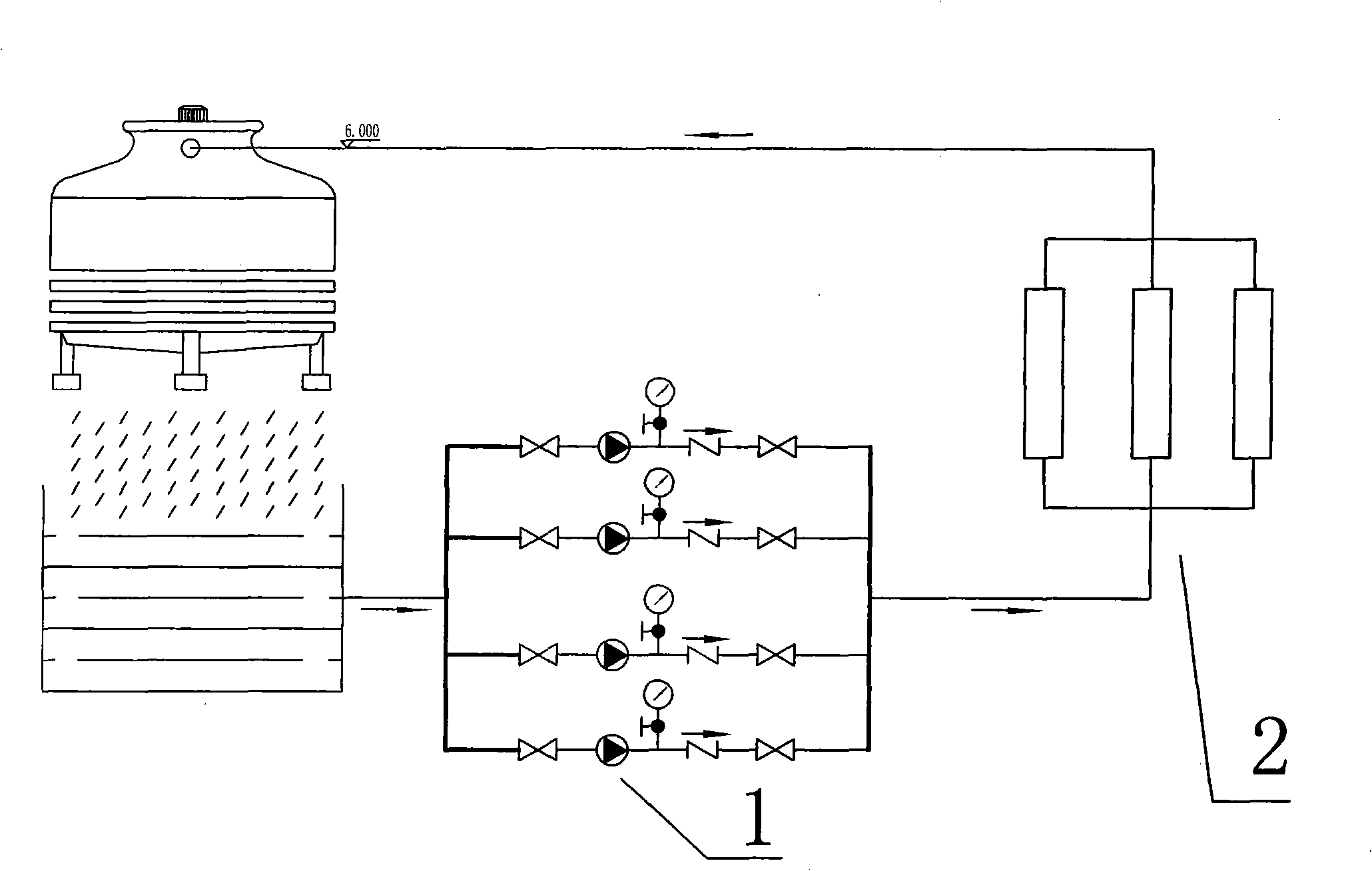
[0037] Embodiment 1, with reference to figure 1 As shown, the central air-conditioning water delivery system optimization technology includes three steps:

[0038] 1. Data collection of central air-conditioning water supply system, which includes cooling water pump 1 and chiller unit 2. The pressure of cooling water pump 1 is collected through a high-precision pressure gauge. The pressure of existing cooling water pump 1 is 0.35MPa, with a pressure punch Collect data on the inlet and outlet pressure of pipe sections, valves and chillers, and collect data on the inlet and outlet temperature of chiller 2 through an infrared thermometer. The existing temperature difference is 3°C;

[0039] 2. The analysis technology of the central air-conditioning water supply system is to establish the model of the central air-conditioning water supply system, and the analysis content is to calculate the pressure through the formula: H=h f + h d + h s + h m

[0040] Calculate the pressure o...

Embodiment 2

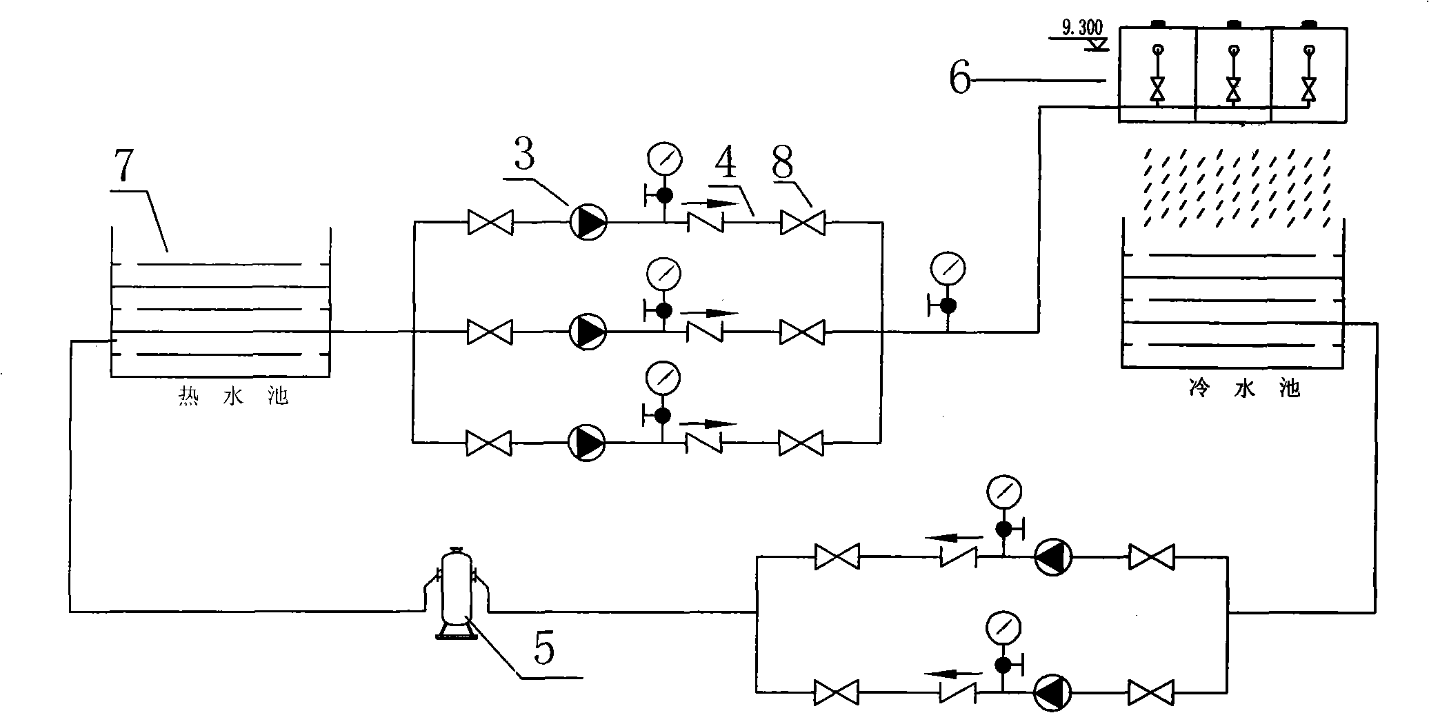
[0042] Embodiment 2, with reference to figure 2 As shown, the blast furnace return water system optimization technology includes three steps:

[0043] 1. Data collection of the backwater system of the blast furnace, data collection of the pump station 3, pipeline 4, terminal equipment 5, cooling tower 6, and water pool 7 through tools. The high-precision pressure gauge collects data on the outlet pressure of the hot water pump in the pumping station 3, the pressure puncher collects data on the pressure behind the valve 8, the ultrasonic flowmeter collects data on the water volume of the system, and the multi-functional electric energy meter monitors the actual consumption of the motor. Power for data collection.

[0044] 2. Blast furnace backwater system analysis technology, establish a backwater system model, the analysis content is to calculate the head of the cooling water pump through the pressure calculation formula, H=h 1 + h 2 + h 3 + h 4 =9.3+1+1+2=13.3m,

[004...


PUM


Abstract

The invention relates to an optimization technology of a circulating water conveying system, which carries out detection, analysis and technical optimization to the prior circulating water conveying system, and comprises three steps: 1. data collection of the circulating water conveying system: the data collection of the technical indicators of each part in the circulating water conveying system is carried out by a tool; 2. an analysis technology of the circulating water conveying system comprises a basis and means, and an analysis content, the basis and the means are used for establishing a model of the circulating water conveying system or a local solid water model, the analysis content is to judge whether the water conveying system has local circulation or high and low pressure mixing, and to carry out the analysis and the calculation to the unnecessary water loss; 3. the optimization technology of the circulating water conveying system is to carry out optimization to a pump station, a pipeline, a cooling tower, a water pool, a valve and back pressure in the circulating water conveying system. The optimization technology of the invention, by the data collection of each device or line in the water conveying system and carrying out the comparison and the analysis, can find out the unreasonable devices or lines to propose an improved technical proposal and provide a new object to replace the original devices or the lines, thus reducing the energy consumption.

Description

technical field [0001] The invention relates to a water body system, in particular to an optimization technology for a circulating water body delivery system. Background technique [0002] Cooling circulating water systems are widely used in process cooling and cooling of equipment and devices. In this technical field, there is little difference in pump efficiency between my country and advanced countries, but there is a big gap in system operation efficiency. According to statistics, the system efficiency in developed countries is about 75%, while that in my country is only about 40%. The root cause of the low system efficiency lies in the backwardness of system design concept, technical means, project decision-making and system operation management. [0003] Due to the uncertain factors in the design and the unstable performance of related equipment, pumps with a capacity larger than the system requirements are often used. In the actual operation process, large horses and ...

Claims


Application Information

Patent Timeline
Patent Type & Authority Applications(China)
IPC IPC(8): F24F3/00C21B7/10
Inventor 杨宝良胡春成叶培培刘晶晶
Owner 杨宝良
Why Eureka
Try Eureka