Tripod head camera for automatically tracking sound source

A pan-tilt camera and automatic tracking technology, which is applied in the direction of using feedback control, instruments, measuring devices, etc., can solve the problems that it is difficult to realize the automatic tracking and response of the pan-tilt camera, achieve flexible circuit combination, improve sensitivity, prevent interference effect

Active Publication Date: 2009-01-14
TIANJIN YAAN TECH CO LTD
View PDF0 Cites 4 Cited by
  • Summary
  • Abstract
  • Description
  • Claims
  • Application Information

AI Technical Summary

Problems solved by technology

However, in many cases, it cannot meet the special monitoring needs of some users. For example, in a hall or square where no one is on duty at night, the PTZ camera can only monitor one or several targets statically or semi-statically. Respond to random abnormalities, such as unusu

Method used


Image

  • Tripod head camera for automatically tracking sound source
  • Tripod head camera for automatically tracking sound source
  • Tripod head camera for automatically tracking sound source

Examples


Embodiment 1

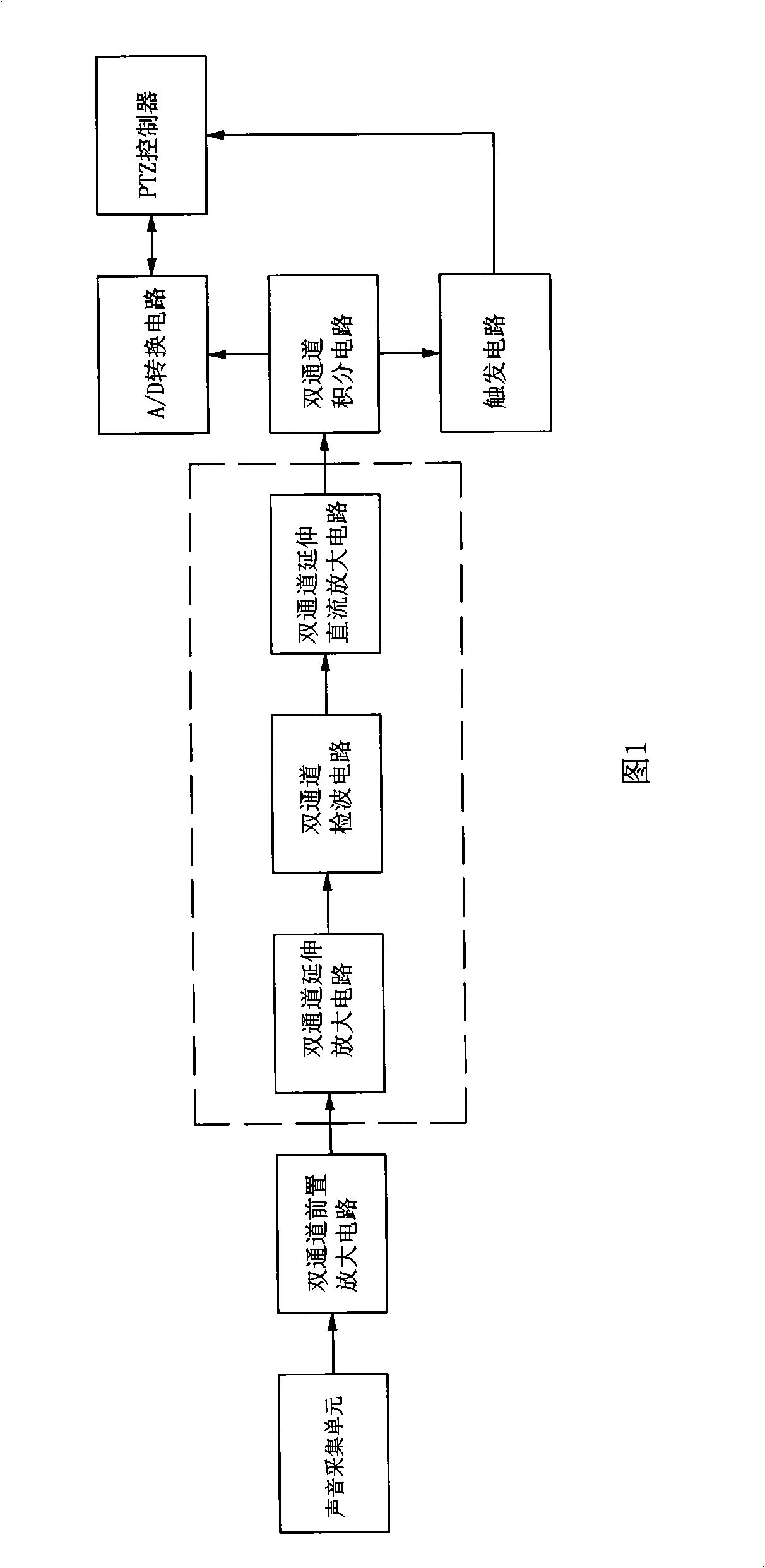
[0034] Embodiment 1, as shown in Figure 1.

[0035] A pan-tilt camera that automatically tracks sound sources, its sound detection circuit is composed of a sound acquisition unit, a dual-channel preamplifier circuit, a sound signal conversion circuit, a dual-channel integration circuit, an A / D conversion circuit, a trigger circuit and a PTZ controller , the sound signal conversion circuit in this embodiment (as shown in the dotted line in Figure 1) is composed of a dual-channel extension amplifying circuit, a dual-channel detection circuit and a dual-channel extending DC amplifying circuit. The connection relationship of each circuit is: the output end of the sound collection unit is connected to the input end of the dual-channel preamplifier circuit, the output end of the dual-channel preamplifier circuit is connected to the input end of the dual-channel extension amplifier circuit, and the output end of the dual-channel extension amplifier circuit is Connect the input end of...

Embodiment 2

[0061] Embodiment 2, as shown in Figure 4.

[0062] The difference between embodiment 2 and embodiment 1 is that the sound signal conversion circuit in embodiment 2 (the dotted line part in Fig. 4) is made up of dual-channel extension amplifying circuit and dual-channel detection circuit, and the input end of dual-channel extension amplifying circuit is connected dual-channel The output end of the channel preamplifier circuit and the output end of the dual-channel extension amplifier circuit are connected to the input end of the dual-channel detection circuit, and the output end of the dual-channel detection circuit is connected to the input end of the dual-channel integration circuit.

Embodiment 3

[0063] Embodiment 3, as shown in Figure 5.

[0064] Embodiment 3 differs from Embodiment 1 in that the sound signal conversion circuit in Embodiment 3 is made up of a dual-channel detection circuit and a dual-channel extended DC amplifier circuit (as shown in the dotted line in Figure 5), and the input end of the dual-channel detection circuit is connected to the dual-channel The output end of the preamplifier circuit and the output end of the dual-channel detection circuit are connected to the input end of the dual-channel extended DC amplifier circuit, and the output end of the dual-channel extended DC amplifier circuit is connected to the input end of the dual-channel integral circuit.


PUM


Abstract

The present invention relates to a horizontal stage video camera for automatically tracking voice source, whose voice detection circuit is composed of a voice acquisition unit, a dual-channel preamp circuit, a voice signal conversion circuit, a dual-channel integral circuit, an A/D converting circuit, a triggering circuit and a PTZ controller. The virtual distance between voice signals after expansion of the strength difference is several times or furthermore larger than the physics distance when they are acquired by the voice acquisition unit, the invention takes a simple method to eliminate the disturbance of reflection voice to the main voice source, greatly facilitates the processing of subsequent data and improves the sensitivity of the complete appliance; the invention has low cost, smaller volume, suitability fro the industrial production and specific adaptation to abnormal voice source or places automatically responding to the specific voice.

Description

technical field [0001] The invention relates to a video monitoring system, in particular to a pan-tilt camera that automatically tracks sound sources. Background technique [0002] People can distinguish the position of sound because people have two symmetrically distributed hearing organs-two ears. When a sound appears, there are some differences in the intensity, time and phase of the sound waves reaching the two ears, and these differential information can help people identify the direction of the sound. However, since the physical distance between the two ears of a person is too small, the above-mentioned intensity difference, time difference and phase difference are not obvious. [0003] The PTZ camera is an important image acquisition device in the security and fire video monitoring system. It can be rotated under the control of the monitoring center or under the control of the program, so as to achieve the purpose of monitoring the target within a certain range. The...

Claims


Application Information

Patent Timeline
IPC IPC(8): H04N7/18G01S5/20G05D3/12
Inventor 崔广庆
Owner TIANJIN YAAN TECH CO LTD
Why Eureka
Try Eureka