Controllable multi-component cathode arc plasma forming apparatus and method

A plasma and cathodic arc technology, applied in the directions of plasma, electrical components, discharge tubes, etc., can solve the problems of difficulty in making composite targets, achieve simple adjustment of component types and density, avoid production difficulties, and simple processing and preparation. Effect

Inactive Publication Date: 2011-09-14
HARBIN INST OF TECH
View PDF0 Cites 0 Cited by
  • Summary
  • Abstract
  • Description
  • Claims
  • Application Information

AI Technical Summary

Problems solved by technology

[0003] The purpose of the present invention is to provide a controllable multi-element cathodic arc plasma forming device and its method to solve the problem that the existing multi-element composite film layer adopts the method of compound multi-element target material, and the composite target material is difficult to manufacture

Method used


Image

  • Controllable multi-component cathode arc plasma forming apparatus and method
  • Controllable multi-component cathode arc plasma forming apparatus and method
  • Controllable multi-component cathode arc plasma forming apparatus and method

Examples


specific Embodiment approach 1

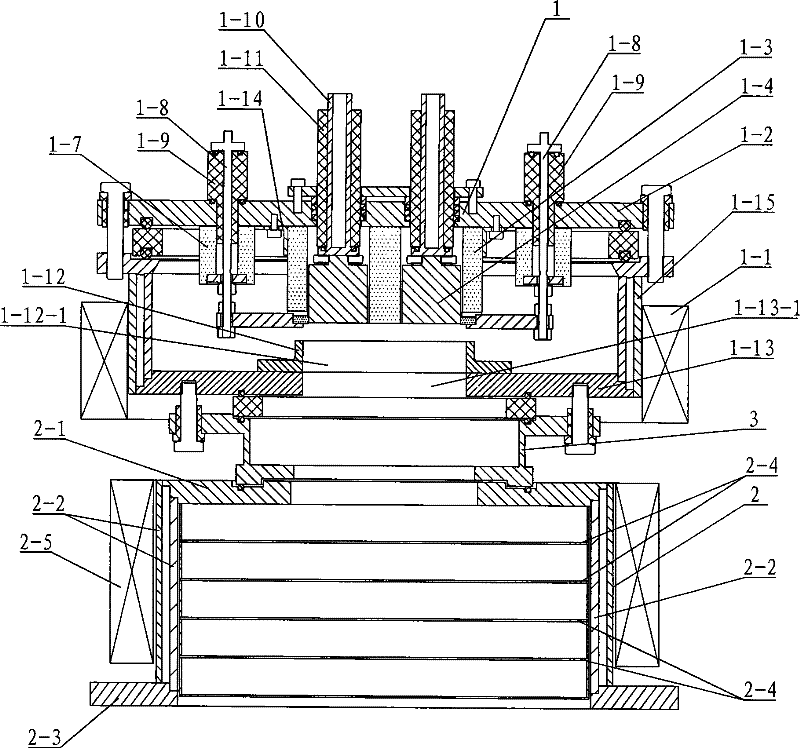
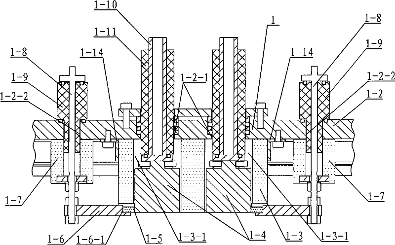
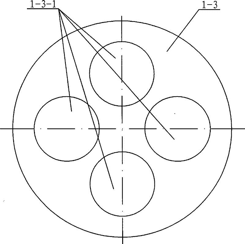
[0008] Specific implementation mode one: combine Figure 1 ~ Figure 3 Describe this embodiment, this embodiment is made up of discharge chamber 1, filter chamber 2 and connection pipe 3, the upper end of connection pipe 3 is connected with the lower end of discharge chamber 1, the lower end of connection pipe 3 is connected with the upper end of filter chamber 2, discharge chamber 1 consists of a magnetic field coil 1-1, an upper cover 1-2, a cathode protection sleeve 1-3, a cathode 1-4, a trigger insulating block 1-5, a trigger plate 1-6, a trigger rod insulating sleeve 1-7, and a trigger rod 1 -8. Composed of trigger rod outer casing 1-9, cathode seat 1-10, cathode insulating sleeve 1-11, anode 1-12, anode seat 1-13, cathodic protection sleeve seat 1-14 and anode cylinder 1-15, The upper cover 1-2 is provided with a cathode seat hole 1-2-1 and a trigger rod hole 1-2-2, and the cathode protection sleeve 1-3 is provided with a cathode hole 1-3-1, and the cathode protection sle...

specific Embodiment approach 2

[0009] Specific implementation mode two: combination figure 2 Describe this embodiment, the cathode seat hole 1-2-1 and the trigger rod hole 1-2-2, the cathode 1-4, the trigger insulating block 1-5, the trigger plate 1-2 on the upper cover 1-2 of the present embodiment 6. The number of trigger rod insulating sleeves 1-7, trigger rods 1-8, trigger rod outer casings 1-9, cathode seats 1-10, and cathode insulating sleeves 1-11 is four to six. This design makes the cathodes 1-4 mutually isolated and connected with different discharge power sources externally, and the discharge current of each cathode 1-4 can be adjusted independently. In this way, the composition of the multivariate mixed plasma in the region of the anode port can be changed by selecting different cathode materials, and the density of the components in the multivariate mixed plasma can be achieved by controlling the discharge current of different cathodes. In addition, 4-6 cathodes 1-4 can obtain a plasma densit...

specific Embodiment approach 3

[0010] Specific implementation mode three: combination figure 2 Describe this embodiment, the cathode seat hole 1-2-1 and the trigger rod hole 1-2-2, the cathode 1-4, the trigger insulating block 1-5, the trigger plate 1-2 on the upper cover 1-2 of the present embodiment 6. There are four trigger rod insulating sleeves 1-7, trigger rods 1-8, trigger rod jackets 1-9, cathode seats 1-10, and cathode insulating sleeves 1-11. This value is to make the plasma density formed by the cathode arc discharge obtained by cathodes 1-4 optimal, so that the rate of film deposition is greatly improved.


PUM

PropertyMeasurementUnit
magnetic flux densityaaaaaaaaaa

Abstract

The invention provides a controllable multi-component cathode arc plasma generating apparatus and method thereof, relates to plasma generating apparatus and method. Composite multi-component target material mode is adopted in current multi-component composite membrane preparation, but the composite target material is difficult to make, and the aim of the invention is to solve the problem. The apparatus is characterized in that: the cathode connecting to cathode base is disposed in arc chamber under the cathode; a triggering board is also disposed in the arc chamber; the arc chamber is connected to filtering chamber through a connection pipe. The method comprises: vacuumizing the arc chamber to 1*10<-1>Pa; loading 4KV trigger pulse on to the trigger electrode to ignite the cathode, to formmulti-component cathode arc plasma in the filtering chamber while the discharge current is 40-200A and the filtering magnetic field strength is 200 gauss. The invention adopts multiple pure metal cathodes as cathode, simplifies preparation, avoids preparation difficulty of composite multi-component cathode caused by is high hardness. The multi-component cathode arc plasma generated in the invention is simple in component and density adjustment.

Description

technical field [0001] The invention relates to a plasma forming device and method. Background technique [0002] The multi-component composite film layer has high hardness and stability at high temperature, and is the main film layer used in parts such as high-speed milling machine tools. The multi-component composite film generally adopts the preparation method of a composite target. For example, to synthesize a titanium aluminum nitrogen (TiAlN) film layer, a titanium aluminum (TiAl) target must be used. Due to the high hardness of the composite target, the processing performance is poor, and the composite target The processing of the target material is very difficult. In addition, the optimization of the composition and structure of the composite film layer must also be obtained by changing the structure of the target material, and the preparation of targets with different components is also a difficult point of research. Contents of the invention [0003] The purpose...

Claims


Application Information

Patent Timeline
Patent Type & Authority Patents(China)
IPC IPC(8): H05H1/32H05H1/34H05H1/28H01J37/32
Inventor 王浪平王小峰解志文
Owner HARBIN INST OF TECH
Why Eureka
Try Eureka