Top pulling device in pipe bender

The technology of a jacking device and a pipe bending machine is applied in the field of pipe bending machines, which can solve the problems of inability to carry out and process, and achieve the effect of reducing the amount of thinning and avoiding the rupture of the pipe wall.

Inactive Publication Date: 2009-01-21
JIANGSU HEFENG MECHANICAL MAKING
View PDF0 Cites 2 Cited by
  • Summary
  • Abstract
  • Description
  • Claims
  • Application Information

AI Technical Summary

Problems solved by technology

When the grabbing claw die 5 in this push device grabs the pipe, the length of the pipe is required not to be too short, because the pipe is too tube, and the grabbing claw die 5 will touch the pipe bending die when bending the pipe, and the pipe cannot be bent. conduct
Therefore, the current pipe bending machine cannot process short pipes, that is, short pipes with a short rear end, especially short pipes with a bending radius ≤ 1.5 times the outer diameter of the pipe.

Method used


Image

  • Top pulling device in pipe bender
  • Top pulling device in pipe bender
  • Top pulling device in pipe bender

Examples


Embodiment Construction

[0012] Specific embodiments of the present invention will be described in detail below in conjunction with the accompanying drawings.

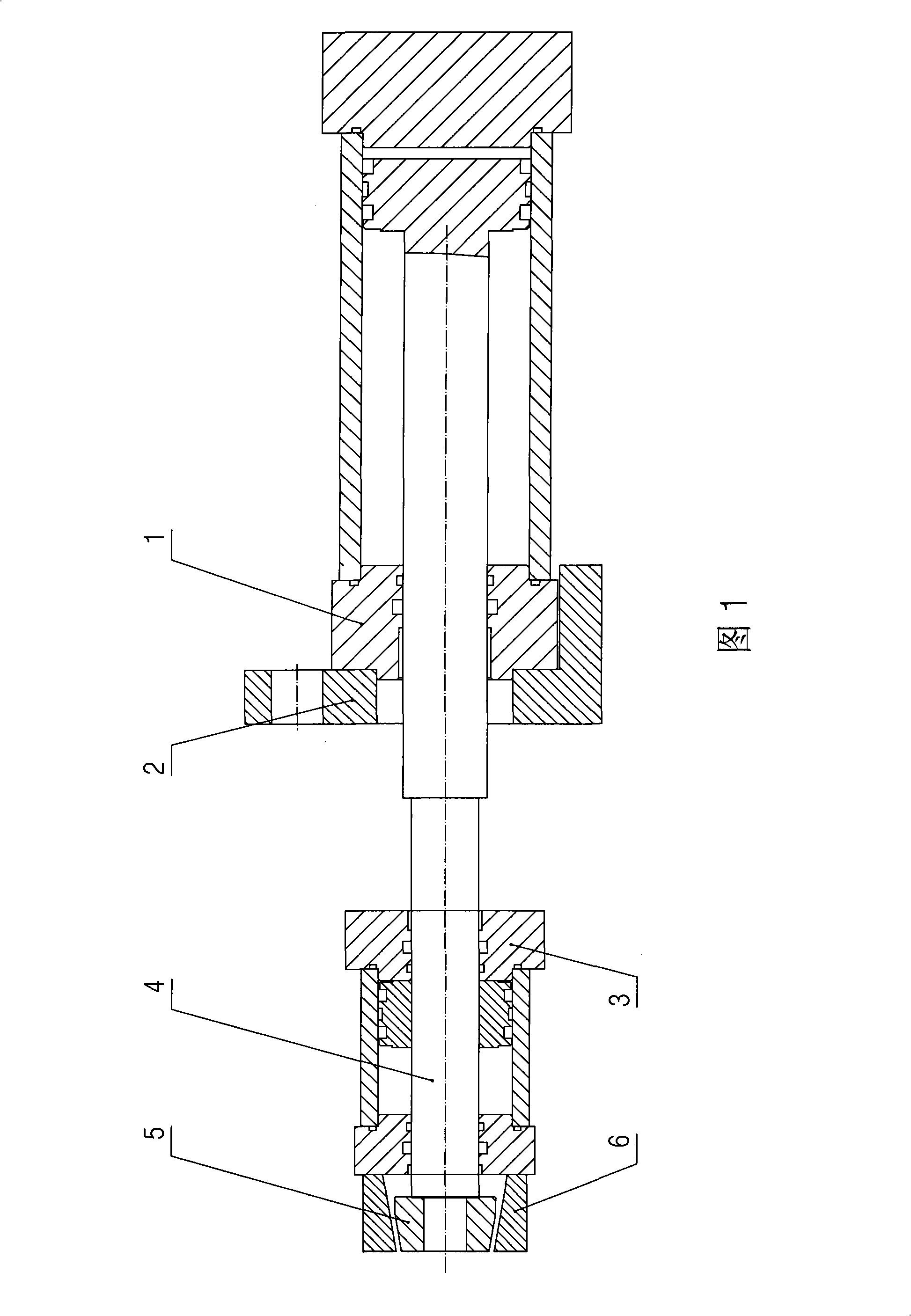
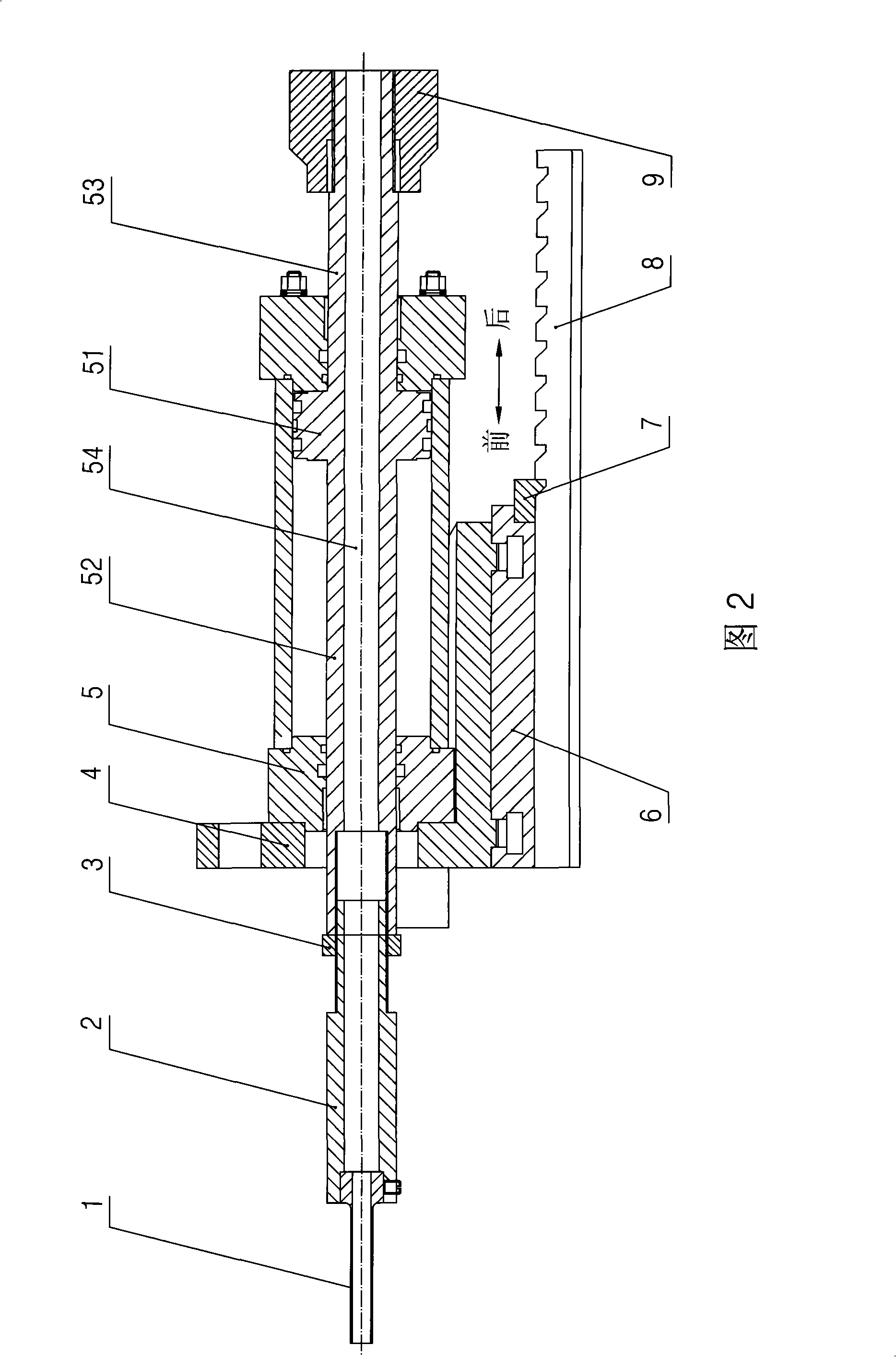
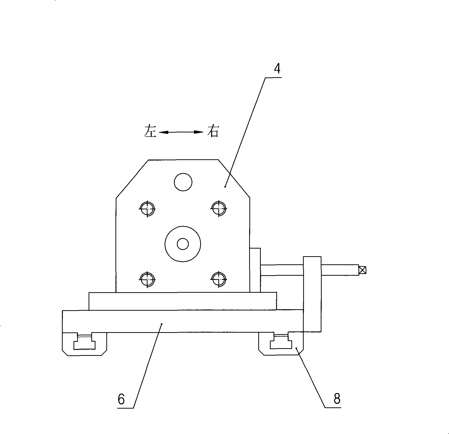
[0013] As shown in Figure 2, the pushing device in the pipe bender of the present invention includes: a pushing pipe 1, an oil cylinder seat 4 and a double-outlet type pushing cylinder 5 arranged on the oil cylinder seat 4, and the pushing cylinder 5 The piston 51 and the piston rods 52 and 53 on the left and right sides of the piston are provided with a through operation hole 54, and the end of the left piston rod 52 is connected with the push pipe 2, and the push pipe 2 is connected with the push pipe 1 , the inner hole of the push pipe 1 communicates with the inner hole of the push connecting pipe 2, the inner hole of the pushing connecting pipe 2 communicates with the operating hole 54, and the end of the right side piston rod 53 is threadably provided with a limit nut 9; The oil cylinder base 4 is movably set on the slide plate 6 through ...


PUM


Abstract

The invention discloses a pushing device in a pipe bending machine, which can cause the pipe bending machine to bend short pipes; the pushing device comprises a pushing pipe, an oil cylinder base and a dual-outlet type pushing oil cylinder which is arranged on the oil cylinder base; a piston of the pushing oil cylinder and piston rods which are arranged at the left side and the right side of the piston are provided with perforated operation holes; the end part of the piston rod at the left side is provided with the pushing pipe; the internal hole of the pushing pipe is communicated with the operation hole; the end part of the piston rod at the right side is provided with a position limit nut by a thread; the oil cylinder base is movably arranged on a sliding plate which is movably arranged on a rack; the rack is provided with a positioning tooth; the side part of one side of the positioning tooth is embedded in the positioning concave trough of the sliding plate. A pushing connecting pipe with a hollow structure is also arranged between the pushing pipe and the piston rod. The pipe bending machine installed with the pushing device of the invention can be used for processing the short pipes, especially for the short pipes with the bending radius which is equal to or less than 1.5 times of the external diameter of the pipe.

Description

technical field [0001] The invention relates to a pipe bending machine, in particular to a pushing device in the pipe bending machine. Background technique [0002] As we all know, when the pipe bender bends small-radius pipes, it needs to use a jacking device. As shown in Figure 1, its structure usually includes: a jacking cylinder 1 set on a jacking seat 2 and a double-outlet grasping cylinder 3, One end of the piston rod 4 of the material grabbing cylinder 3 is provided with a tapered material grabbing claw mold 5, and the other end of the piston rod 4 of the material grabbing cylinder 3 is arranged with the piston rod of the top material oil cylinder 1, and one part of the material grabbing cylinder 3 The side is also provided with the taper sleeve 6 that cooperates with the claw mold 5 of grasping material. When bending the pipe, the material grabbing cylinder 3 moves first, so that the cylinder body of the material grabbing cylinder 3 moves backward with the taper sle...

Claims


Application Information

Patent Timeline
Patent Type & Authority Applications(China)
IPC IPC(8): B21D7/00B21D7/16
Inventor 林洪才周炳生
Owner JIANGSU HEFENG MECHANICAL MAKING
Why Eureka
Try Eureka