Synchronous control method and apparatus for web rotary printing press
A synchronous control, web-fed technology, applied in rotary printing presses, general parts of printing machinery, printing presses, etc., can solve the problems of increasing operator burden, bad printed parts, etc., and achieve the effect of reducing the number of production and reducing the burden
- Summary
- Abstract
- Description
- Claims
- Application Information
AI Technical Summary
Problems solved by technology
Method used
Image

Examples
Embodiment 1
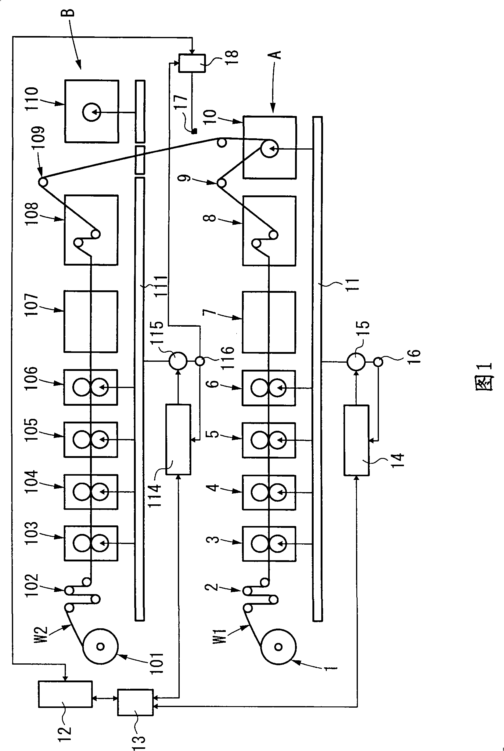
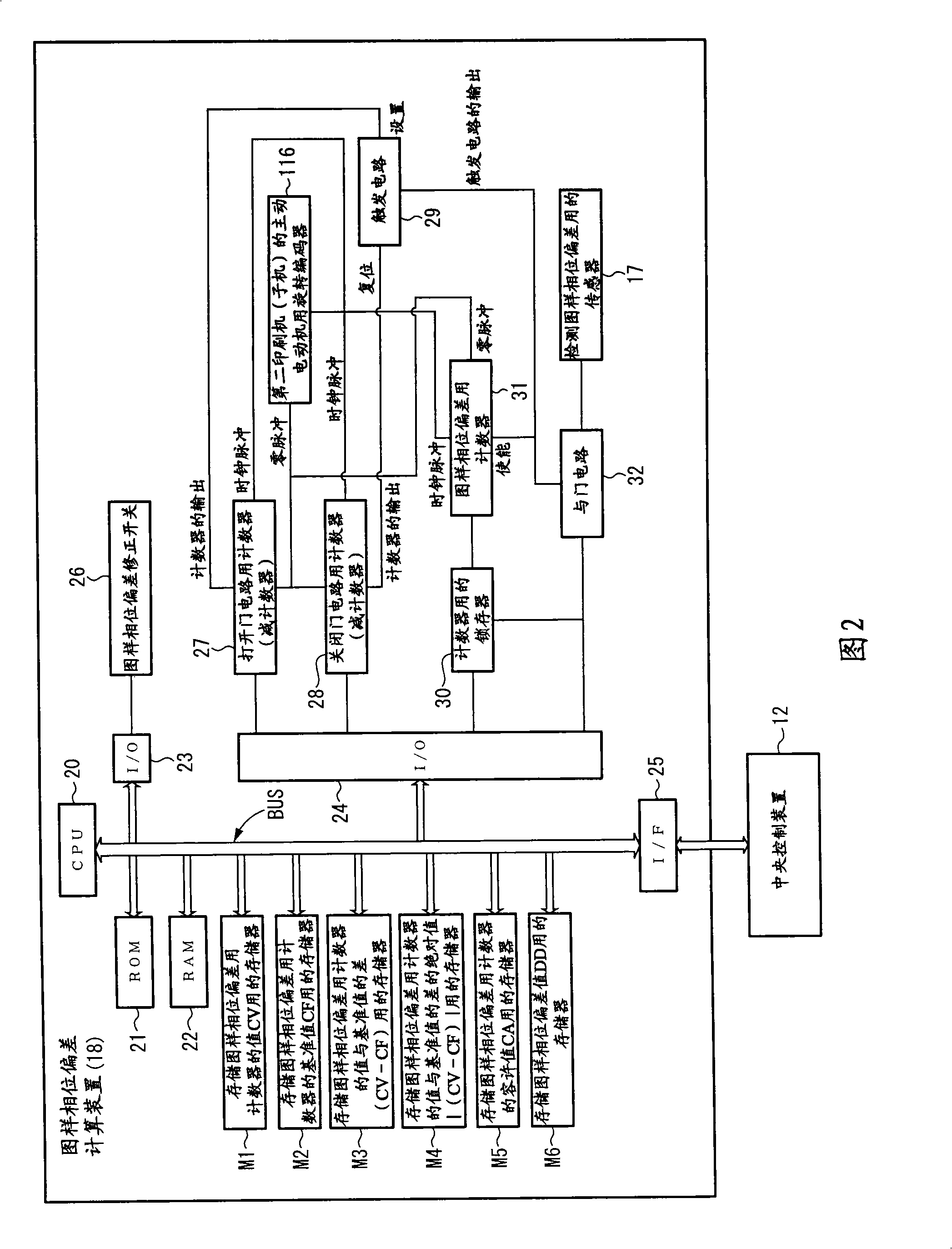
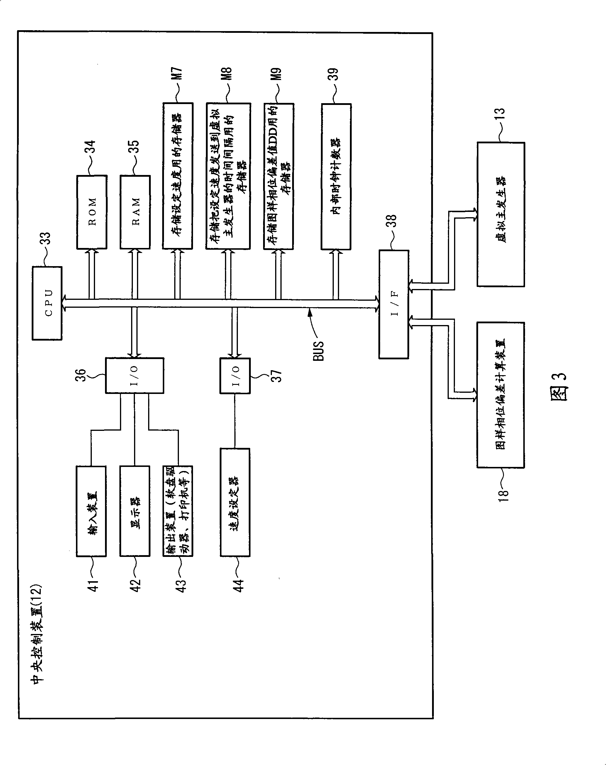
[0105] Fig. 1 is a schematic structural diagram of a synchronous control device of a web rotary printing machine shown in Embodiment 1 of the present invention, Fig. 2 is a block diagram of a pattern phase deviation calculation device, and Fig. 3 is a block diagram of a central control device, Figure 4 is a block diagram of the virtual main generator, and Fig. 5 is a block diagram of the drive control devices of the master machine and the slave machine, Image 6 It is the flow chart of the operation of the pattern phase deviation calculation device, Fig. 7 (a) is the flow chart of the operation of the central control device, Fig. 7 (b) is the flow chart of the operation of the central control device, Fig. 8 (a) is the flow chart of the virtual main generator Action flow chart, Fig. 8 (b) is the action flow chart of virtual main generator, Fig. 9 (a) is the action flow chart of virtual main generator, Fig. 9 (b) is the action flow chart of virtual main generator, Figure 10 It ...
Embodiment 2
[0194] Fig. 12 is a schematic structural diagram of a synchronous control device of a web rotary printing machine shown in Embodiment 2 of the present invention, Fig. 13 is a block diagram of a pattern phase deviation calculation device, and Fig. 14 is a block diagram of a central control device, Figure 15 Fig. 16 is a block diagram of a virtual master generator, and Fig. 16 is a block diagram of drive control devices for each unit of a master machine and a slave machine. Figure 17 is a flow chart of the operation of the pattern phase deviation calculation device. Fig. 18 (a) is the action flowchart of the central control device, Fig. 18 (b) is the action flow chart of the central control device, Fig. 19 (a) is the action flow chart of the virtual main generator, Fig. 19 (b) is the virtual The action flow chart of the main generator, Figure 20 (a) is the action flow chart of the virtual main generator, Figure 20 (b) is the action flow chart of the virtual main generator, F...
Embodiment 3
[0283] Fig. 23 is a schematic structural diagram of a synchronous control device for a web rotary printing machine shown in Embodiment 3 of the present invention, Fig. 24 is a block diagram of a pattern phase deviation calculation device, and Fig. 25 is a block diagram of a drive control device for a main printing press, Fig. 26 is a block diagram of a drive control device of a slave printer, Figure 27It is a flow chart of the operation of the pattern phase deviation calculation device, Figure 28 (a) is a flow chart of the operation of the drive control device of the main printing press, Figure 28 (b) is a flow chart of the operation of the drive control device of the main printing press, Figure 29 ( a) is a flow chart of the operation of the drive control device of the main printing press, and FIG. 29(b) is a flow chart of the operation of the drive control device of the main printing press. Figure 30 It is the flow chart of the operation of the drive control device of the ...
PUM
 Abstract
Description
Claims
Application Information
 - R&D
- Intellectual Property
- Life Sciences
- Materials
- Tech Scout
- Unparalleled Data Quality
- Higher Quality Content
- 60% Fewer Hallucinations
Browse by: Latest US Patents, China's latest patents, Technical Efficacy Thesaurus, Application Domain, Technology Topic, Popular Technical Reports.
© 2025 PatSnap. All rights reserved.Legal|Privacy policy|Modern Slavery Act Transparency Statement|Sitemap|About US| Contact US: help@patsnap.com