
Vacuum auxiliary molding technique produced by large-sized sandwich composite material

A composite material, vacuum-assisted technology, applied in the field of composite material molding, to achieve the effect of avoiding sag, avoiding dry spots, and beautiful appearance

Active Publication Date: 2009-01-28
725TH RES INST OF CHINA SHIPBUILDING INDAL CORP
View PDF1 Cites 57 Cited by
  • Summary
  • Abstract
  • Description
  • Claims
  • Application Information

AI Technical Summary

Problems solved by technology

[0005] The purpose of the present invention is to propose a vacuum-assisted forming process for large-scale sandwich composite parts, so as to overcome the defects in the existing sandwich composite forming process

Method used


Image

  • Vacuum auxiliary molding technique produced by large-sized sandwich composite material
  • Vacuum auxiliary molding technique produced by large-sized sandwich composite material

Examples


Embodiment 1

[0016] The size of the composite sandwich structure is 600mm×1000mm, the foam core material is polyurethane foam, and the thickness is 15mm; the surface density of the upper and lower panels is 220g / m 2 The S glass fiber satin weave cloth has a thickness of 2 mm after molding; the vacuum-assisted forming scheme of the present invention is used to implement the overall molding of the sandwich structure of composite materials.

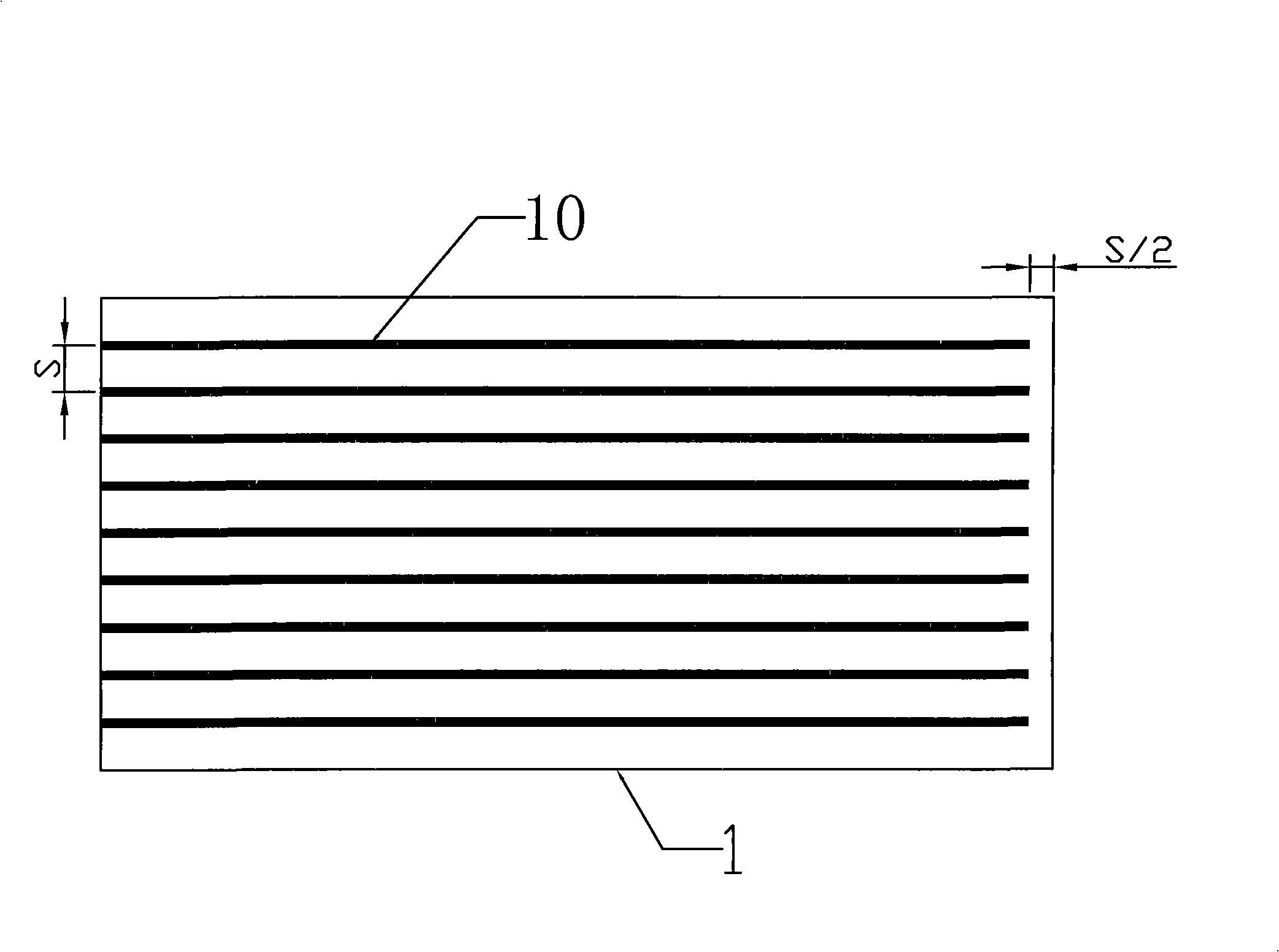
[0017] 1. Open a set of grooves along the length direction of the polyurethane foam core material. The width of the grooves is 4mm, the depth is 1mm, the distance between the grooves is 60mm, and the distance between the foam core material and the grooves is 30mm.

[0018] 2. Spread 10 layers of S glass fiber satin cloth cut according to size on the mold that has been cleaned and coated with release agent; place the processed polyurethane foam core material on the glass fiber fabric, and place the groove surface In contact with the fabric; then spread 10...

Embodiment 2

[0026] The size of a composite sandwich structure is 1600mm×2000mm, the foam core material is polyvinyl chloride foam, the thickness is 15mm, and the surface density of the upper and lower panels is 220g / m 2 The S glass fiber satin cloth, the thickness of the panel after forming is 1mm, and the vacuum-assisted forming scheme of this patent is used to implement the overall forming of the composite sandwich structure.

[0027] 1. Open a set of grooves along the length direction of the polyvinyl chloride foam core material. The width of the groove is 5mm, the depth is 4mm, the distance between the grooves is 100mm, and the distance between the foam core material and the groove is 50mm.

[0028] 2. Spread 5 layers of cut S glass fiber satin cloth on the mold that has been cleaned and coated with release agent; place the grooved PVC foam core material on the glass fiber fabric, and place the groove The surface of the groove is in contact with the fabric; then lay 5 layers of S-fibe...


PUM

PropertyMeasurementUnit
sizeaaaaaaaaaa
thicknessaaaaaaaaaa
sizeaaaaaaaaaa

Abstract

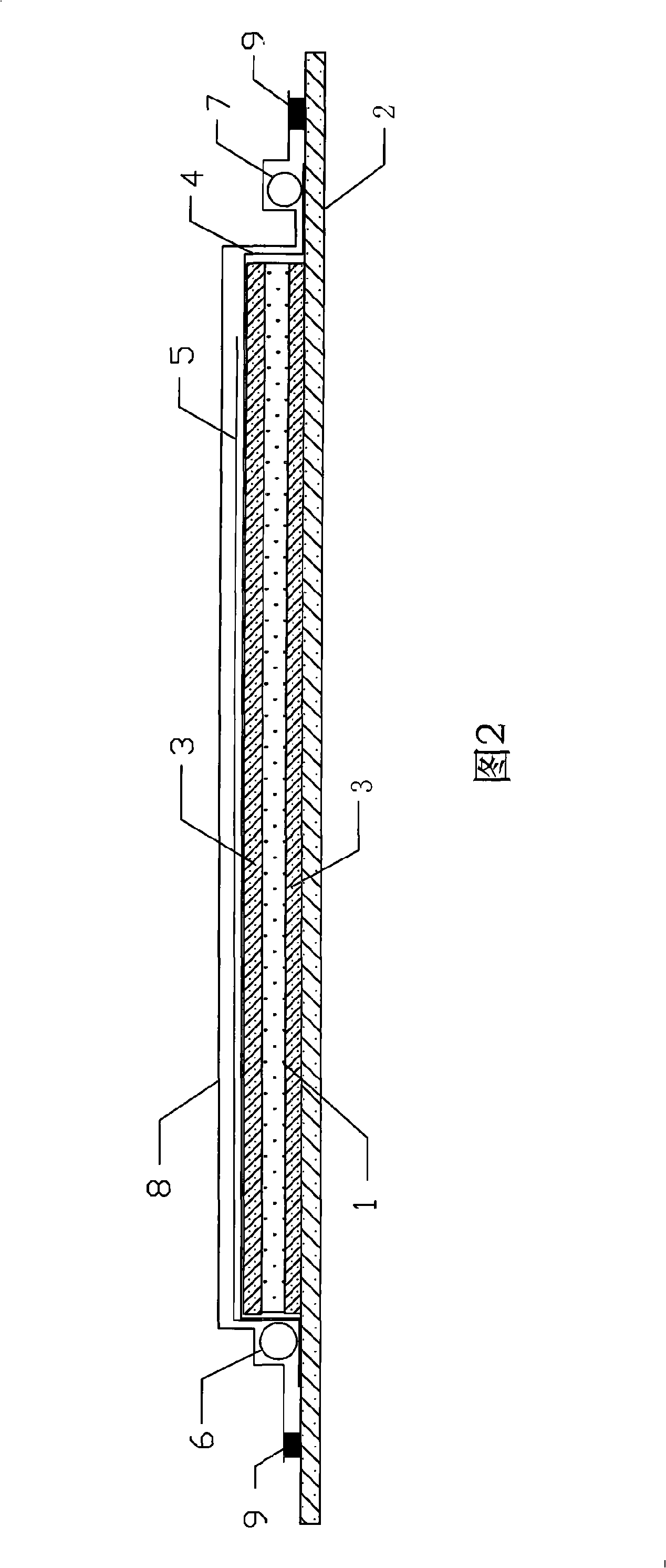
The invention provides a vacuum assistant resin infused method for molding a large part of sandwich composite materials as follows: a set of grooves parallel to each other are arranged at the bottom of the foam core material; fiber fabrics are paved on a processed die according to the specified thickness, and then the grooved foam core material is arranged on the already-paved fiber fabrics, wherein, the machined surface of the grooves of foam core material contacts to the already-paved fiber fabrics, and then the fiber fabrics with a specified thickness are paved on the foam core material; a conduction pipe is arranged at one foam core material end with grooves and a vacuum pipe is arranged at the other end; sealed vacuum bag film and sealed adhesive tape are adopted to seal the fiber fabrics; when the vacuum pressure in the sealed bag film is equal to or less than negative 0.095Mpa, resin solution is inducted to the resin conduction system consisting of the conduction pipe and the conduction cloth after being poured with glue; after the resin immerses the fiber fabrics completely, glue pouring and evacuation are stopped; after the poured-in resin is heat-released and solidified, sandwich composite materials are obtained after 24 hours solidification under indoor temperature condition.

Description

technical field [0001] The invention belongs to the technical field of composite material forming, and mainly proposes a vacuum-assisted forming process method for large sandwich composite material parts. Background technique [0002] Foam sandwich composite materials are generally made of three layers of materials, the upper and lower layers are panels made of high-strength, high-modulus materials, and the middle layer is low-density foam plastics to form a structural whole. Due to the existence of the foam core material, the two panels maintain a certain distance, so that the moment of inertia of the section is increased, which not only improves the bending stiffness of the structure, but also makes full use of the material strength, so that the material can achieve the ideal structural performance while reducing weight , improved material utilization. At present, it has been widely used in the fields of aircraft, ships and missiles. [0003] The traditional preparation ...

Claims


Application Information

Patent Timeline
Patent Type & Authority Applications(China)
IPC IPC(8): B29C70/36
Inventor 王利张兴刚张建设
Owner 725TH RES INST OF CHINA SHIPBUILDING INDAL CORP
Learn More