
Control device for vehicular power transmitting device

一种传送装置、车辆动力的技术,应用在传动装置控制、通用动力装置的多个不同原动机的布置、动力装置等方向,能够解决电动机很难获得再生量等问题,达到充电容量迅速恢复、防止换档振动、防止再生转矩脱离的效果

Inactive Publication Date: 2009-01-28
TOYOTA JIDOSHA KK
View PDF1 Cites 9 Cited by
  • Summary
  • Abstract
  • Description
  • Claims
  • Application Information

AI Technical Summary

Problems solved by technology

In addition, due to the limited torque of the motor, it is difficult for the motor to obtain sufficient regeneration (power generation)

Method used


Image

  • Control device for vehicular power transmitting device
  • Control device for vehicular power transmitting device
  • Control device for vehicular power transmitting device

Examples


Embodiment Construction

[0037] Various embodiments of the present invention will now be described in detail with reference to the accompanying drawings.

[0038]

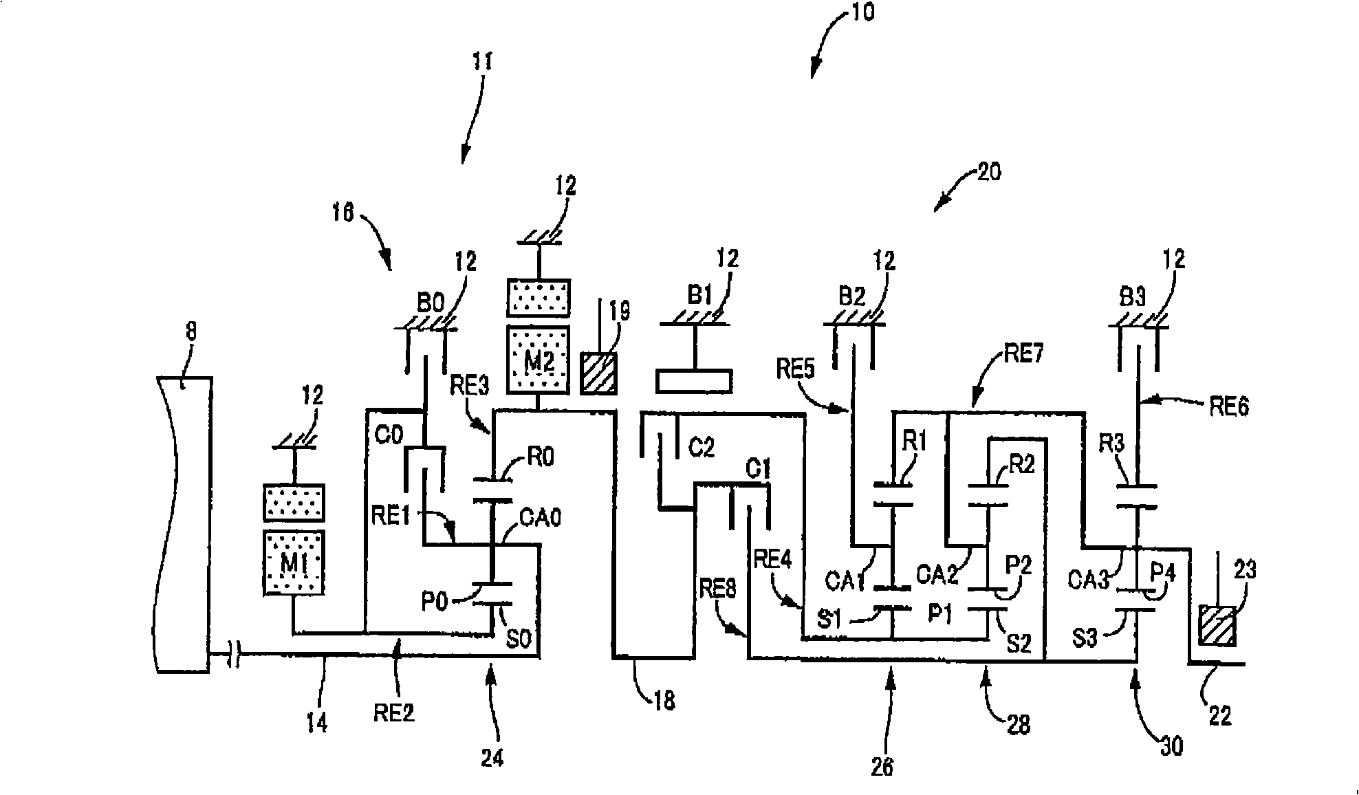
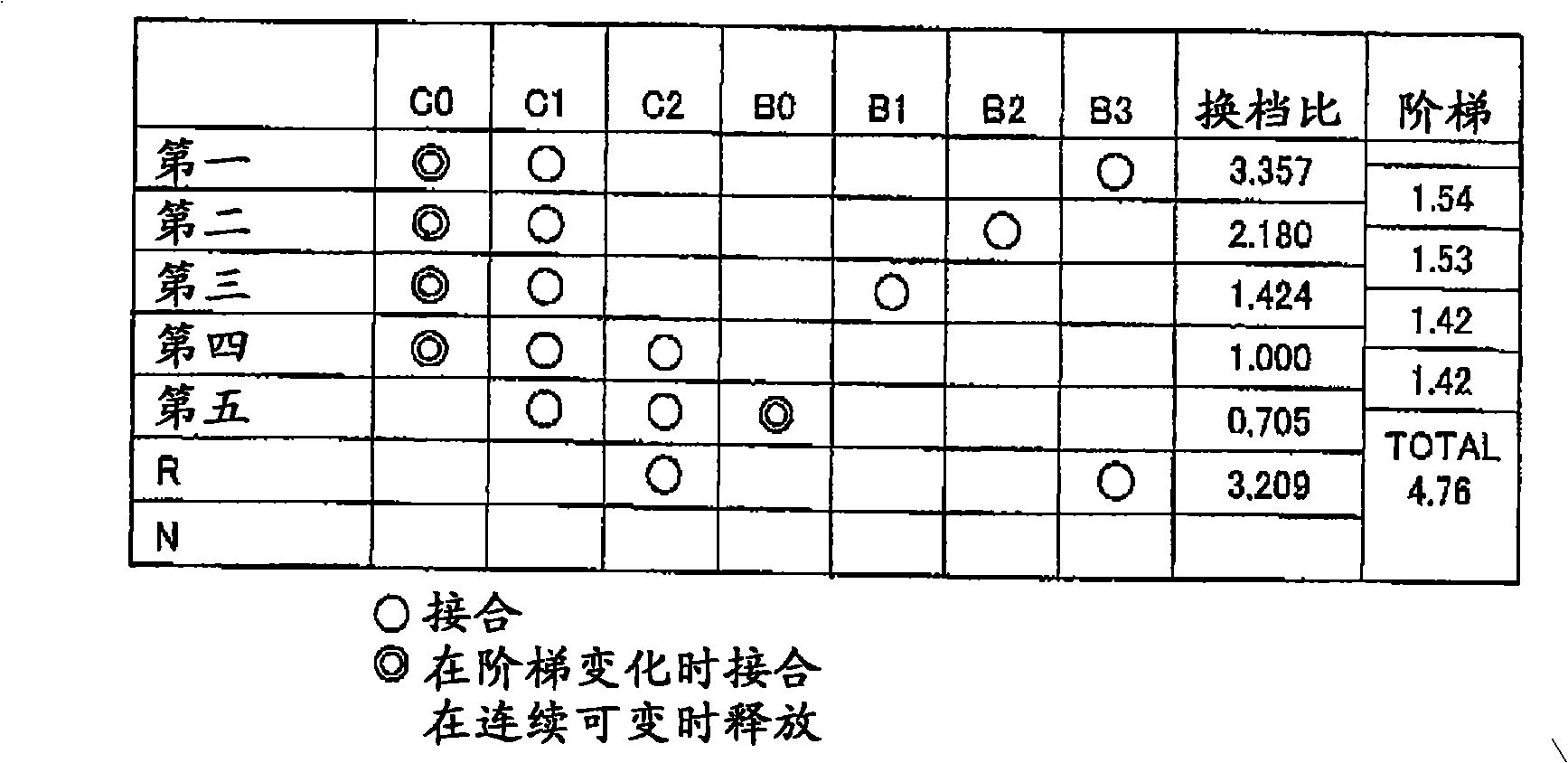
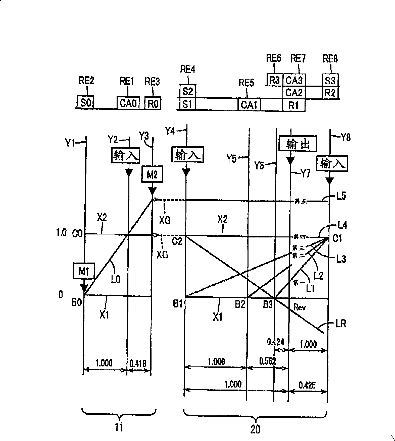
[0039] figure 1 It is a perspective view showing a shift mechanism 10 constituting a part of a drive apparatus for a hybrid vehicle to which a control device according to an embodiment of the present invention is applied. Such as figure 1 As shown, the shift mechanism 10 includes: an input shaft 14 as an input rotary element; a differential portion 11, which is directly connected to the input shaft 14 or indirectly connected thereto through a pulsation absorbing damper (vibration damping device) not shown. On: the automatic shift part 20, which passes through the power transmission element (transmission shaft) 18 and the differential mechanism 11 and the drive wheel 38 (see Figure 6 ) between the power transmission path is connected in series as a step change type transmission; the output shaft 22, which is connected to the automati...


PUM


Abstract

This invention relates to a control device for a vehicular power transmitting device. The control device has shifting-point altering means 108 operative such that when a second electric motor M2 is operated with priority to obtain a charging efficiency and / or electric power generating efficiency, a shifting point for a vehicle to run under a decelerating state (during a coast running state) is altered to a point on a higher vehicle speed than that at which a shifting point for a running-performance-conscious state is set. Therefore, when the second electric motor M2 is operated with priority for generating electric power, a downshift is initiated at a high vehicle speed than that at which the downshift is initiated at a shifting point for a running-performance-conscious state. This increases a rotation speed NM2 of the second electric motor M2, resulting in an increase in regeneration amount (electric power generation amount) of the second electric motor M2.

Description

technical field [0001] The present invention relates to a control device for a vehicular power transmission device having a shift portion constituting part of a power transmission path between a driving force source and drive wheels, and an electric motor connected to the power transmission path. In particular, the present invention relates to a technology that performs regeneration control for a coast running mode so as to compatibly realize increased regeneration amount and drivability. Background technique [0002] There is known a control device for a vehicle power transmission device comprising: a shift portion constituting a portion of a power transmission path between a driving force source and drive wheels; an electric motor connected to the shift portion; enter. For example, Patent Document 1 (Japanese Patent Laid-Open No. 2006-2913) discloses such a hybrid vehicle power transmission device. With the control device disclosed in Patent Document 1, the differential ...

Claims


Application Information

Patent Timeline
Patent Type & Authority Applications(China)
IPC IPC(8): F16H61/02B60W20/00B60W10/10B60K6/445B60K6/547B60L15/20B60L50/16B60W10/08B60W10/18B60W10/26F16H59/74F16H61/10F16H61/68F16H61/684F16H61/686F16H63/50
CPCB60W2520/10B60W2710/081B60W10/115B60W2510/104B60W2510/1015B60K6/445B60K6/547B60L2240/421F16H61/0213Y10S903/945B60W10/08Y02T10/6221B60W2510/0657B60L2240/441Y02T10/6239B60K6/48F16H3/728F16H2037/0873B60L2240/486B60K6/365B60W20/00B60L2240/443Y02T10/7258B60K1/02Y02T10/642B60W2510/0638Y02T10/62Y02T10/64Y02T10/72B60K2006/4833B60W20/13B60W10/26
Inventor 松原亨柴田宽之熊崎健太田端淳
Owner TOYOTA JIDOSHA KK
Learn More