
Refrigeration heat pump system

A heat pump system, cooling and heating technology, applied in heat pumps, refrigerators, refrigeration components, etc., can solve the problems of slow defrosting speed, slow defrosting speed, increase the defrosting time of the whole machine, etc., to achieve fast defrosting and even defrosting. , cleverly designed effects

Inactive Publication Date: 2009-01-28
GUANGDONG MIDEA ELECTRIC APPLIANCES CO LTD
View PDF0 Cites 4 Cited by
  • Summary
  • Abstract
  • Description
  • Claims
  • Application Information

AI Technical Summary

Problems solved by technology

[0002] Existing domestic heating and cooling air conditioners and heat pump water heaters will frost on the outdoor heat exchanger after working for a period of time when heating. In order not to affect the normal operation of the outdoor heat exchanger, defrosting treatment is required every once in a while. , in the process of defrosting, the compressor sends hot steam of the refrigerant to the outdoor heat exchanger to melt the frost layer on the heat exchanger. Since the temperature of the refrigerant gradually decreases during the defrosting process, the defrosting effect of the refrigerant is also gradually weakened. , so that the inlet side of the refrigerant will defrost quickly, while the defrosting speed of the outlet side of the refrigerant is very slow. Because the defrosting speed of the refrigerant outlet of the heat exchanger is slow, the defrosting time of the whole machine will be increased.

Method used


Image

  • Refrigeration heat pump system

Examples


Embodiment

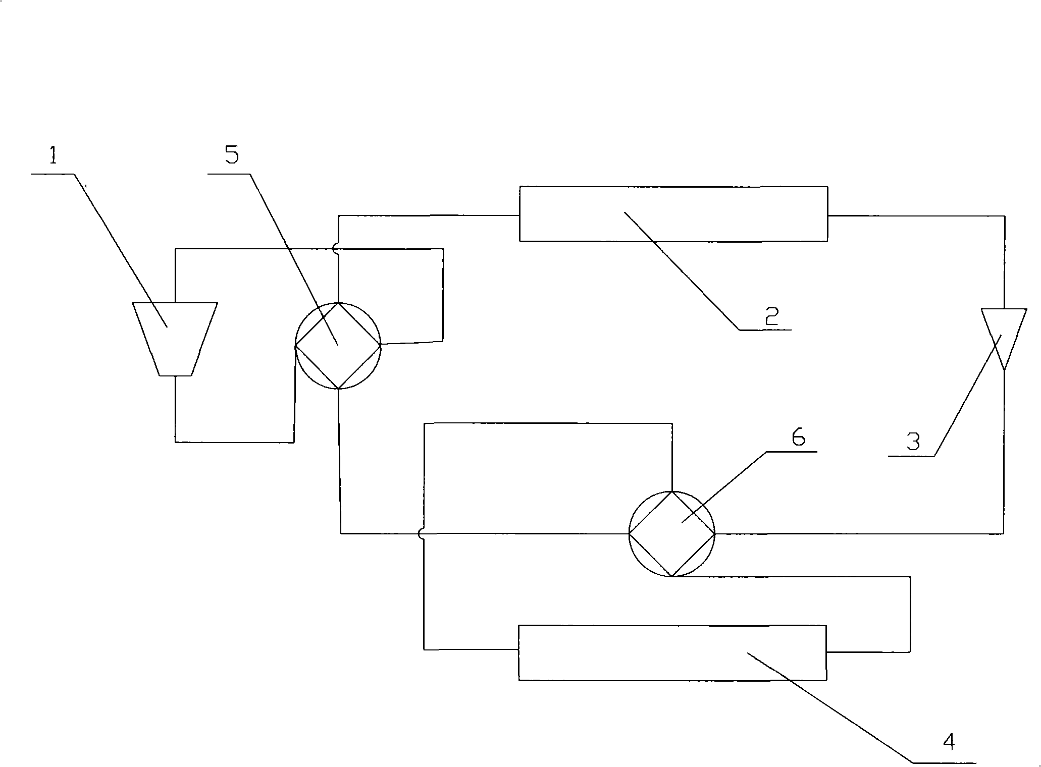
[0010] The principle diagram of the present invention is as figure 1 As shown, the refrigeration heat pump system of the present invention at least includes a compressor 1, an indoor heat exchanger 2, a throttling component 3, an outdoor heat exchanger 4 and a four-way reversing valve 5 for cooling and heating, wherein the refrigerant inlet and refrigerant outlet of the compressor 1 Connect with the two interfaces of the four-way reversing valve 5, the third interface of the four-way reversing valve 5 is connected with one end of the indoor heat exchanger 2, and the other end of the indoor heat exchanger 2 is connected with the throttling component 3 , wherein the throttling component 3 is connected to the outdoor heat exchanger 4 through the second four-way reversing valve 6, the refrigerant inlet and the refrigerant outlet of the outdoor heat exchanger 4 are connected to the two ports of the second four-way reversing valve 6, and the second The third port of the second four-...


PUM


Abstract

The invention relates to a refrigeration heat-pump circulatory system which at least comprises a compressor, an indoor heat exchanger, a throttling part, an outdoor heat exchanger and a cold and hot four-way reversing valve, wherein, a cooling medium inlet and a cooling medium outlet of the compressor are connected with two interfaces of the cold and hot four-way reversing valve; a third interface of the cold and hot four-way reversing valve is connected with one end of the indoor heat exchanger, the other end of the indoor heat exchanger is connected with the throttling part which is connected with the outdoor heat exchanger by a second out-way reversing valve; the cooling medium inlet and the cooling medium outlet of the outdoor heat exchanger are connected with two interfaces of a second four-way reversing valve; a third interface of the second four-way reversing valve is connected with the throttling part; a fourth interface of the second four-way reversing valve is connected with a fourth interface of the cold and hot four-way reversing valve. In the refrigeration heat-pump circulation system of the invention, when the cooling medium inlet of the outdoor heat exchanger is defrosted to a certain phase, reversing is carried out by the second four-way reversing valve to the cooling medium inlet and the cooling medium outlet of the outdoor heat exchanger to quicken the original defrosting speed at the cooling medium outlet of the outdoor heat exchange, thus ensuring that the defrosting can be finished effectively at both the cooling medium inlet and the cooling medium outlet of the outdoor heat exchanger and leading the defrosting to be more even and faster.

Description

technical field [0001] The invention belongs to the field of refrigeration and air conditioning, in particular to a refrigeration heat pump defrosting circulation system, which belongs to the transformation technology of the cold heat pump system. Background technique [0002] Existing domestic heating and cooling air conditioners and heat pump water heaters will frost on the outdoor heat exchanger after working for a period of time when heating. In order not to affect the normal operation of the outdoor heat exchanger, defrosting treatment is required every once in a while. , in the process of defrosting, the compressor sends hot steam of the refrigerant to the outdoor heat exchanger to melt the frost layer on the heat exchanger. Since the temperature of the refrigerant gradually decreases during the defrosting process, the defrosting effect of the refrigerant is also gradually weakened. , so that the inlet side of the refrigerant will defrost quickly, but the defrosting sp...

Claims


Application Information

Patent Timeline
Patent Type & Authority Applications(China)
IPC IPC(8): F25B13/00F25B30/02F25B47/02
Inventor 宋锐
Owner GUANGDONG MIDEA ELECTRIC APPLIANCES CO LTD
Learn More