

Modularization error-tolerance type permanent magnet switch magnetic linkage straight line motor
A technology of permanent magnet switch and linear motor, which is applied in the direction of electrical components, electromechanical devices, electric components, etc., can solve the problems of low full rate, low utilization rate of permanent magnets, magnetic flux leakage at the end, etc., and achieve flexible control, easy and low cost Mass production, low mutual inductance effect
Inactive Publication Date: 2010-11-10
ZHEJIANG UNIV
View PDF0 Cites 14 Cited by
- Summary
- Abstract
- Description
- Claims
- Application Information
AI Technical Summary
Problems solved by technology
However, in the traditional permanent magnet switch flux linkage linear motor, the end flux leakage is serious, the utilization rate of the permanent magnet is low, and the slot fullness rate of two sets of windings placed in one slot is low
Method used
View moreImage
Smart ImageViewing Examples

Examples
Embodiment Construction
Login to View More PUM
 Abstract
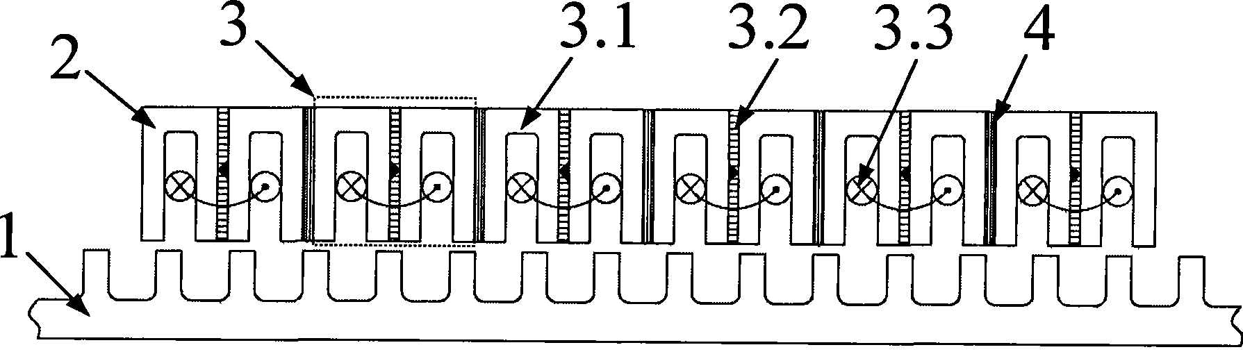
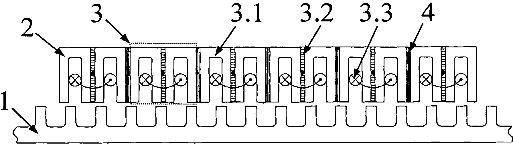
The invention discloses a modularized fault-tolerance type permanent-magnet switched magnetic linkage linear motor, comprising a stator and a mover, wherein the stator is a flat plate or a cylinder formed by a toothed groove type iron core, the mover is a flat plate or a cylinder formed by a plurality of modules and reluctance pieces which are arranged at intervals, each module comprises two reversed U-shaped iron cores, a permanent magnet clamped between the two U-shaped iron cores, and a three-phase armature winding, armature teeth are formed on the sides of the two U-shaped iron core for clamping the permanent magnet, auxiliary teeth are formed on the sides of the two U-shaped iron core sides for clamping the reluctance piece, the three-phase armature winding is wound on the armature teeth, the auxiliary teeth are not wound with a winding, and N poles and S poles of adjacent modules are arranged at intervals. In the linear motor, the coil and the permanent magnet are arranged on the mover part, the stator part only consists of an iron core lamination at low cost and is particularly suitable for a long-distance linear motion drive system; in addition, the modularized design brings convenience to the assembly and is easy to implement the large-scale production.
Description
Modular fault-tolerant permanent magnet switch flux linkage linear motor technical field The invention relates to a permanent magnet brushless DC motor, in particular to a modular fault-tolerant permanent magnet switch flux linkage linear motor, belonging to the technical field of motor manufacturing. Background technique The motor is the main driving component in the transmission system, and choosing a suitable motor can improve the performance of the entire transmission system. In many linear motion situations, traditional rotary motors need to use certain mechanical transmission components, such as screw rods, to convert the rotary motion output by the rotary motor into a linear motion, and then finally use it to drive the linear motion. The problems brought about by this include increased volume and weight of the system, high noise, low control accuracy caused by large mechanical inertia, high maintenance costs, and short service life. A more reasonable solution is to...
Claims
Login to View More Application Information
Patent Timeline
 Patent Type & AuthorityPatents(China)
IPC IPC(8): H02K41/03
Inventor沈建新王灿飞
OwnerZHEJIANG UNIV