Magnetic resonance quick spin echo imaging method

A technology of spin echo and imaging method, applied in magnetic resonance measurement, material analysis through resonance, magnetic property measurement, etc., which can solve problems such as image blurring

Inactive Publication Date: 2009-02-04
EAST CHINA NORMAL UNIV
View PDF0 Cites 21 Cited by
  • Summary
  • Abstract
  • Description
  • Claims
  • Application Information

AI Technical Summary

Problems solved by technology

[0007] The purpose of the present invention is to solve the problems of "echo amplitude phase oscillation" and "transverse relaxat

Method used


Image

  • Magnetic resonance quick spin echo imaging method
  • Magnetic resonance quick spin echo imaging method
  • Magnetic resonance quick spin echo imaging method

Examples


Embodiment Construction

[0015] The present invention will be further described below in conjunction with accompanying drawing

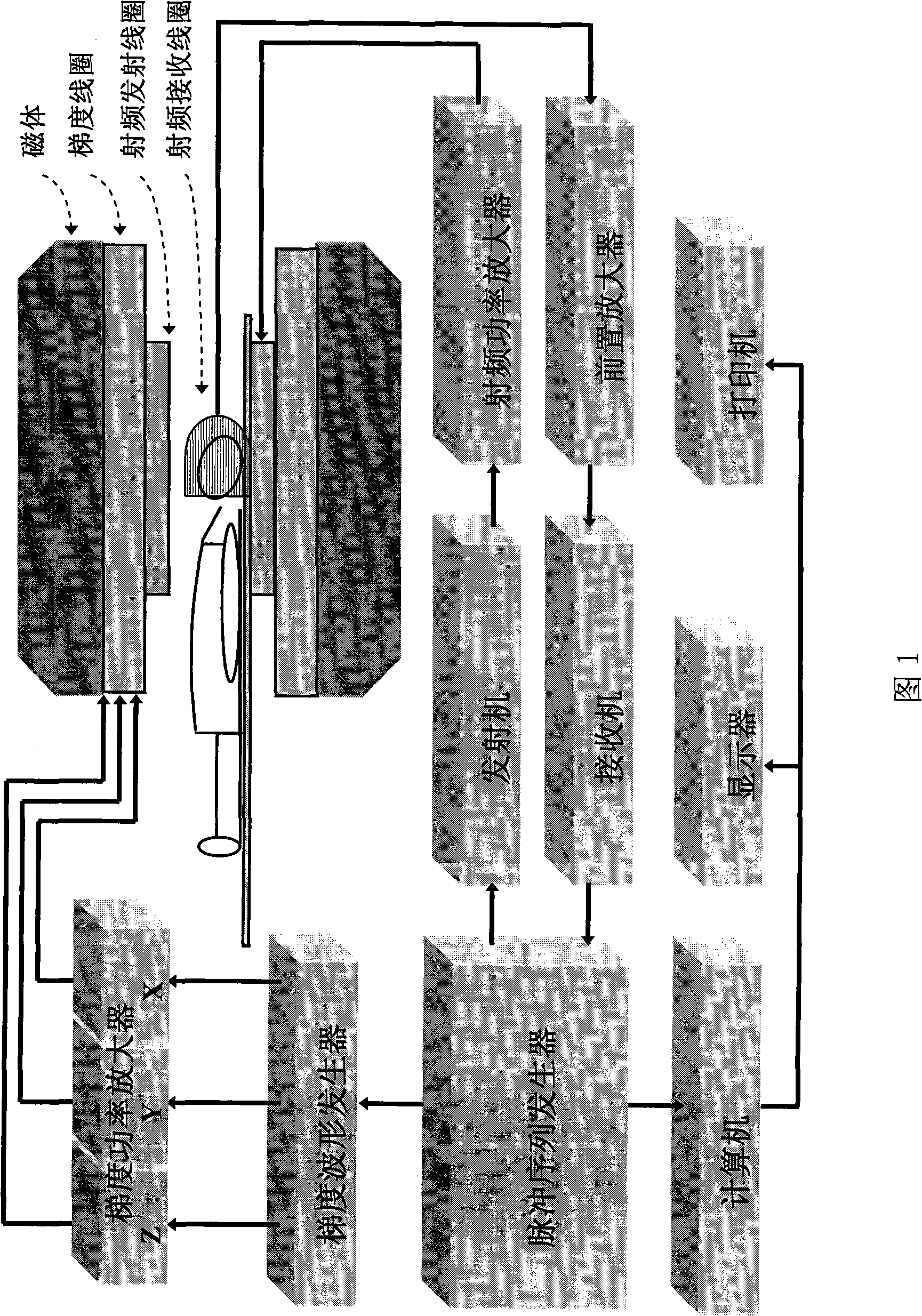
[0016] The present invention is based on the magnetic resonance imaging (MRI) system structure as shown in accompanying drawing 1, and is combined with it and does following operation steps:

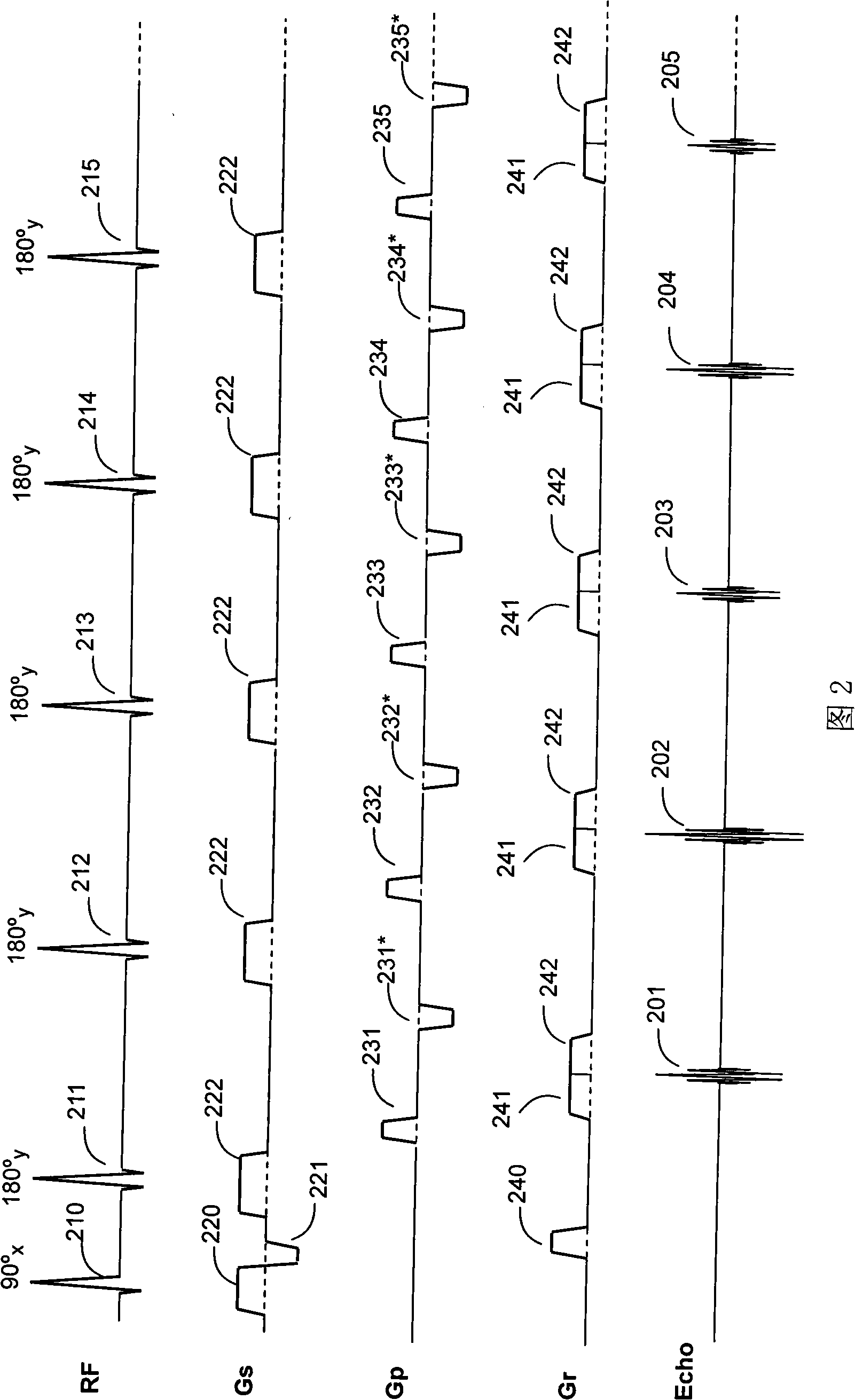
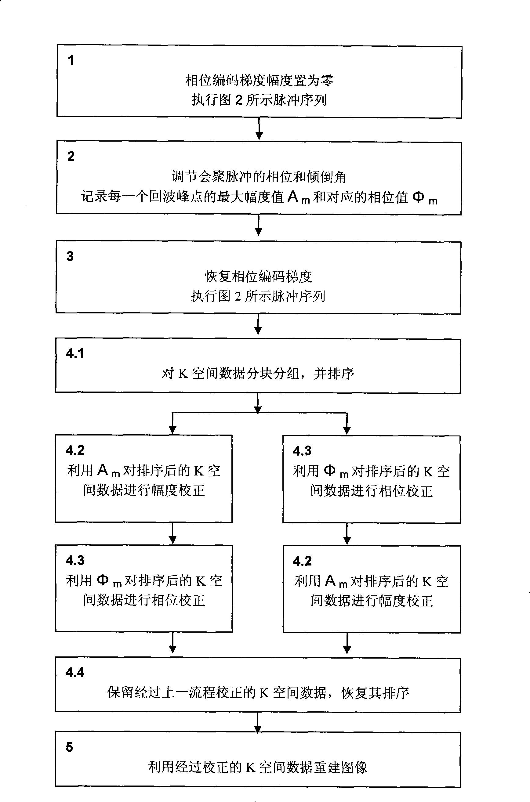
[0017] (1) Set the phase encoding gradient amplitude to zero, use the FSE pulse sequence to perform pre-scanning, and record the amplitude values ​​of the peak points of each echo signal on the echo chain;

[0018] (2) Adjust the phase and dumping angle of the converging pulse, so that the amplitude of each echo signal peak point on the echo chain reaches the maximum value, and record the amplitude value A of each echo signal peak point at this time m and phase value Φ m ;

[0019] (3) Restore the phase encoding gradient, scan with FSE pulse sequence, and obtain K-space data;

[0020] (4) Amplitude A of each echo signal peak point obtained by step (2) m and phase Φ m , to correct ...


PUM


Abstract

The invention relates to the field of magnetic resonance imaging technique, in particular to a magnetic resonance fast spin echo (FSE) imaging method, comprising the steps as follows: 1. phase coding gradient amplitude is reset, pre-scanning is carried out by FSE pulse sequence, the amplitude value of each etch signal peak on the echo chain is recorded; 2. the phase and inclination angle of convergence pulse is adjusted so as to lead the amplitude of each echo signal peak on the echo chain to achieve the maximum value, when the amplitude value Am and phase angle Phim of each echo signal peak are recorded; 3. the phase coding gradient is recovered, the scanning is carried out by the FSE pulse sequence, thus gaining the K space data; 4. according to the amplitude Am and Fai<m> of each echo signal peak gained in step 2, the K space data is corrected; 5. image reconstruction is carried out by the corrected K space data thus gaining the magnetic resonance images, etc. The magnetic resonance fast spin echo (FSE) imaging method solves the problems of echo amplitude phase oscillation and image blurring due to transverse relaxation of the prior art.

Description

technical field [0001] The invention relates to the technical field of magnetic resonance imaging, in particular to a magnetic resonance fast spin echo (FSE) imaging method. Background technique [0002] Magnetic resonance imaging (MRI) technology has become a very useful tool in medical diagnosis. Usually, in the magnetic resonance imaging system, when the measured sample (such as human tissue) is in the static magnetic field B 0 (B 0 The direction is defined as the Z-axis direction of the Cartesian coordinate system) when equilibrium is reached, the atomic nuclei (nuclear spins) in the sample are affected by the B 0 Polarized to produce a macroscopic magnetization vector M 0 . m 0 Under the excitation of radio frequency pulses, it is rotated into the horizontal plane (XY plane), and then precesses around the Z axis. A receiving coil is placed around the tested sample, and it will induce the precession signal of the magnetization vector. After the magnetic resonance ...

Claims


Application Information

Patent Timeline
IPC IPC(8): A61B5/055G01R33/20
Inventor 宁瑞鹏李鲠颖
Owner EAST CHINA NORMAL UNIV
Why Eureka
Try Eureka