Vacuum switch tube

A vacuum switch tube and contact technology, applied in the electrical field, can solve the problems of insufficient withstand voltage and difficulty in solving electric field concentration, etc., and achieve the effects of improving high voltage withstand capability, improving current breaking capability, and reducing poor contact.

Active Publication Date: 2009-02-04
BEIJING BOE VACUUM ELECTRONICS CO LTD
View PDF0 Cites 9 Cited by
  • Summary
  • Abstract
  • Description
  • Claims
  • Application Information

AI Technical Summary

Problems solved by technology

However, the contacts in the current vacuum switch tube are often difficult to form a good longitudinal magnetic field for arc extinguishing due to the limitation of the structural shape, and it is difficult to solve the problems of electric field concentration and insufficient withstand voltage during high-voltage breaking.
For the breaking of high-voltage circuits, the existing technology can realize the breaking of 36 kV voltage. For higher voltage circuits, especially the high voltage of 72 kV, there is currently no vacuum switching tube structure that can meet the requirements of effective arc extinguishing during breaking. requirements, which is one of the problems to be solved in the existing vacuum switch technology

Method used


Image

  • Vacuum switch tube
  • Vacuum switch tube
  • Vacuum switch tube

Examples


specific Embodiment 2

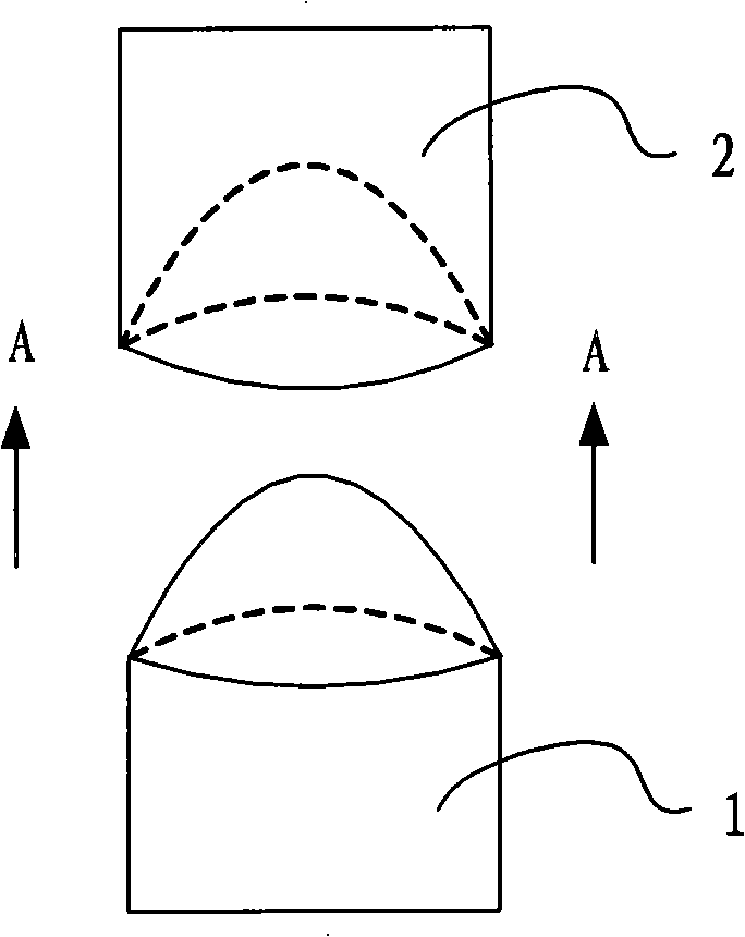
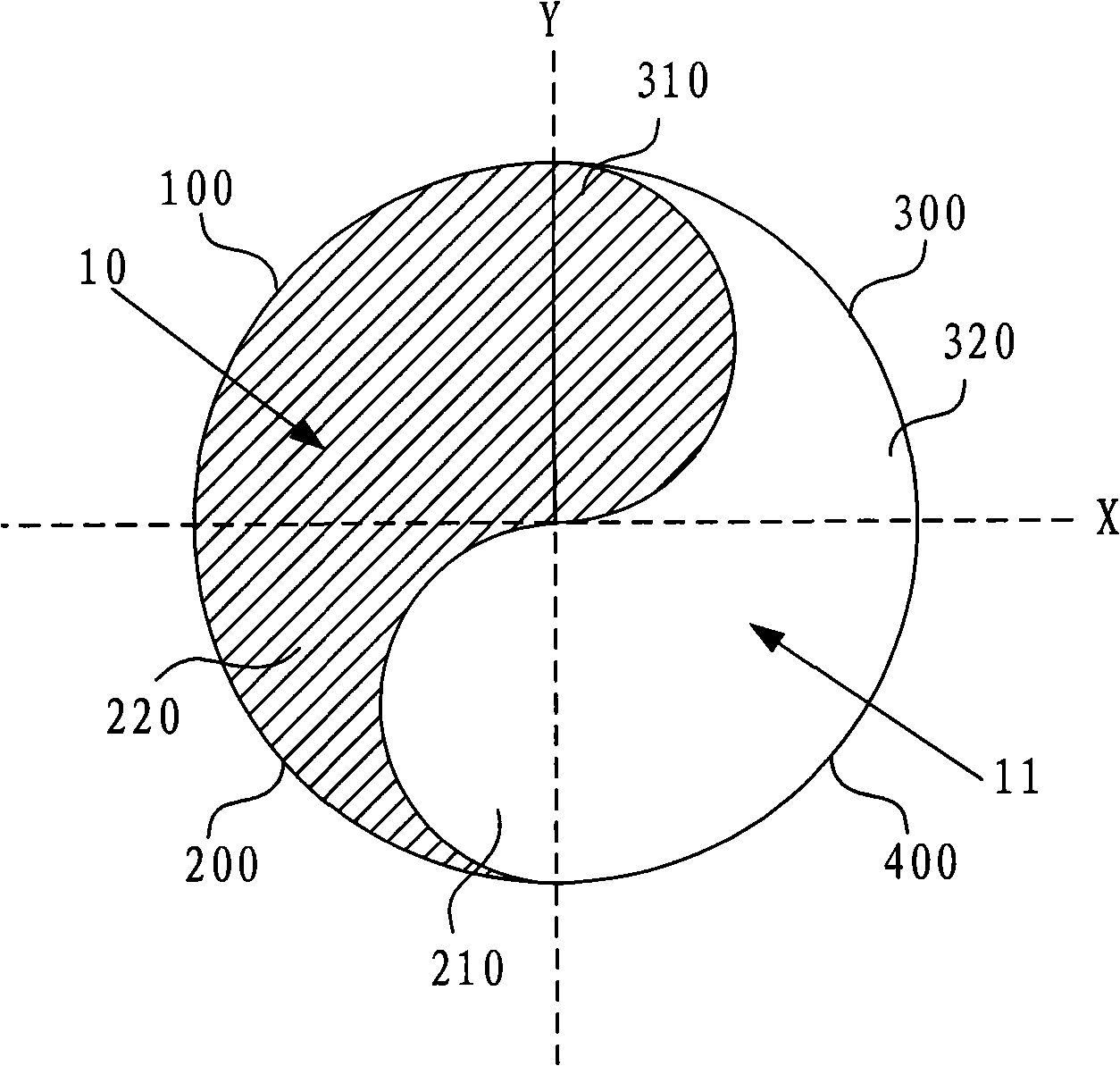
[0029] Figure 4 It is a side view structural schematic diagram of the first contact in the second embodiment of the vacuum switch tube of the present invention. In this embodiment, the contact bodies of the first contact and the second contact are composed of several layers of sheet bodies stacked in sequence, each layer of sheet body is composed of a conductive sheet and a magnetic conductive sheet adjacently combined, and several conductive sheets are composed The conductive part consists of several magnetically conductive sheets. The cross-sectional shape of the conductive sheet and the magnetically conductive sheet and the structural relationship between the conductive part and the magnetically conductive part can adopt the technical scheme in the above-mentioned embodiment, which is a combination of yin and yang fish or Symmetrically arranged, all the sheets are stacked together to form the outer contour shape of the contact, such as Figure 4 Shown is the front end of ...

specific Embodiment 3

[0032] Figure 5 It is a schematic diagram of the cross-sectional structure of the first contact in the third embodiment of the vacuum switch tube of the present invention. On the basis of the second embodiment above, in order to fix the relative position of the conductive part and the magnetically conductive part before the sheet body is melted and solidified, it is also possible to further provide a fixing hole 12 through several sheet bodies on the conductive sheet and the magnetically conductive sheet. A fixed column is inserted in the fixed hole 12, such as Figure 5 As shown, and one end of the fixing column is fixed to the bottom inside the metal shell. The material of the fixing post can be the same as that of the conductive part, such as copper metal.

[0033] The technical solution of this embodiment can simplify the production and manufacture of the contact body. After a plurality of sheet bodies are prepared by a simple molding process, the sheet bodies can be pu...


PUM


Abstract

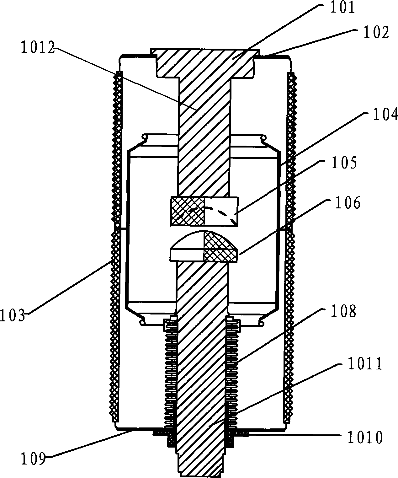
The invention relates to a vacuum switch tube, comprising a first electric conduction pole and a second electric conduction pole. A contact is arranged at one end of the first electric conduction pole and a second contact is arranged at one end of the second electric conduction pole. Each of the first contact and the second contact comprises an electric conduction assembly and a magnetic conduction assembly which are sealed inside a vacuum tube face to face with each other; wherein the front end of the first contact is provided with a convex hemispheroid and the front end of the second contact is provided with a concave hemispheroid which matches with the convex hemispheroid at the front end of the first contact. The electric conduction assembly and the magnetic conduction assembly are matched like Yin-Yang fish in shape. The magnetic conduction assembly of the first contact is arranged face to face with the electric conduction assembly of the second contact, and the electric conduction assembly of the first contact is arranged face to face with the magnetic conduction assembly of the second contact. The surface areas of the contacts of the vacuum switch tube are increased, thus reducing the increase of the resistance caused by poor contact. Meanwhile, a revolving magnetic field is formed between contacts of the convex hemispheroid and the concave hemispheroid, which is good for arc extinguishing, thus improving breaking capacity.

Description

technical field [0001] The invention relates to a vacuum switch tube, in particular to a vacuum switch tube with opposite contacts in an arc-extinguishing chamber, which belongs to the field of electrical technology. Background technique [0002] A switchgear is an important device in a circuit, which plays the role of connecting and disconnecting the circuit. In the process of disconnecting the circuit of the switchgear, the switch tube will generate an arc, which will cause the temperature of the contacts and other components in the switch tube to rise sharply and cause loss, especially in the high-voltage circuit, the arc intensity generated when the line is disconnected It is very large, so that the service life of the switch tube is greatly shortened. Therefore, the switching tube must be extinguished during the circuit switching process. [0003] Most of the current switchgear uses arc extinguishing media such as oil, sulfur hexafluoride, air, semiconductor or vacuum...

Claims


Application Information

Patent Timeline
Patent Type & Authority Applications(China)
IPC IPC(8): H01H33/66H01H33/664H01H33/18H01H1/06
Inventor 任建昌
Owner BEIJING BOE VACUUM ELECTRONICS CO LTD
Why Eureka
Try Eureka