

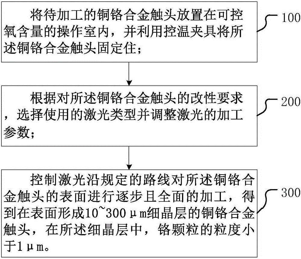
Laser surface modification method of copper-chromium alloy contact
A technology of laser surface modification and copper-chromium alloy, which is applied in the field of material processing, can solve the problems of increased surface roughness of copper-chromium alloy contacts, unstable molten pool, large thermal conductivity of copper, etc., and achieve surface contact resistance and surface resistance. Favorable welding ability, improved electrical performance and breaking current capacity, and improved yield strength
- Summary
- Abstract
- Description
- Claims
- Application Information
AI Technical Summary
Problems solved by technology
Method used
Image

Examples
Embodiment 1
[0051] Step 1, prepare a copper-chromium alloy contact workpiece with a clean surface prepared by melting and casting, the workpiece size is 51 mm in diameter, and 3 mm in thickness; the mass percentage of chromium in it is about 25%, and the particle size is 20-70 μm;
[0052] Step 2, place the above-mentioned workpiece in an Ar gas environment with controllable oxygen content (oxygen content ≤ 1ppm), and fix it with a temperature-controlled fixture with water cooling; set the processing parameters for laser modification, including: power density 6.4×10 6 W / cm 2 , defocus amount -4mm, scanning speed 800mm / min, scanning distance 0.2mm;
[0053] Step 3, start the laser system, and automatically modify the surface of the copper-chromium alloy contact according to the planned movement trajectory; at the same time, turn on the infrared thermometer for temperature measurement, and the test temperature is 875K;
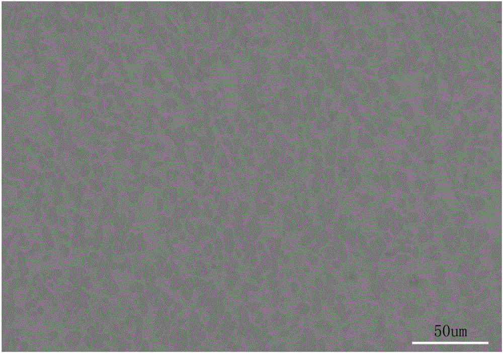
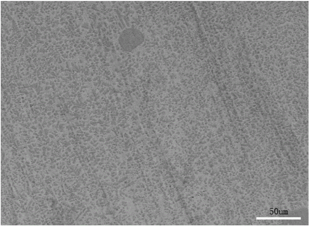
[0054] Step 4, after laser surface treatment, such as figure 2 , 3...
Embodiment 2
[0056] Step 1, prepare a copper-chromium alloy contact workpiece with a clean surface prepared by the infiltration method, the workpiece size is 51 mm in diameter, and 3 mm in thickness; the mass percentage of chromium in this workpiece is about 30%, and the particle size is 80-130 μm;
[0057] Step 2, place the above-mentioned workpiece in an Ar gas environment with controllable oxygen content (oxygen content ≤ 100ppm), and fix it with a temperature-controlled fixture with water cooling; set the processing parameters for laser modification, including: power density 3.5×10 6 W / cm 2 , defocus amount 2mm, scanning speed 8000mm / min;
[0058] Step 3, start the laser system, and automatically modify the surface of the copper-chromium alloy contact according to the planned movement trajectory; at the same time, turn on the infrared thermometer to measure the temperature, and the test temperature is 1853K;
[0059] Step 4, after laser surface treatment, such as Figure 4 , 5 As sh...
Embodiment 3
[0061] Step 1, prepare a copper-chromium alloy contact workpiece with a clean surface prepared by the mixed powder sintering method, the workpiece size is 51 mm in diameter, and 3 mm in thickness; the mass percentage of chromium in it is about 50%, and the particle size is 130-180 μm;
[0062] Step 2, place the above-mentioned workpiece in an Ar gas environment with controllable oxygen content (oxygen content ≤ 400ppm), and fix it with a temperature-controlled fixture with water cooling; set the processing parameters for laser modification, including: power density 8.5×10 5 W / cm 2 , Defocus amount +5mm, scanning speed 15000mm / min;
[0063] Step 3, start the laser system, and automatically modify the surface of the copper-chromium alloy contact according to the planned movement trajectory; at the same time, turn on the infrared thermometer for temperature measurement, and the test temperature is 1128K;
[0064] Step 4, after laser surface treatment, the cross-sectional microst...
PUM
| Property | Measurement | Unit |
|---|---|---|
| particle size | aaaaa | aaaaa |
| surface roughness | aaaaa | aaaaa |
| particle size | aaaaa | aaaaa |
Abstract
Description
Claims
Application Information