
Directional freezing styloid or single-crystal nickel-base high-temperature alloy repairing or coating method

A nickel-based superalloy, directional solidification technology, applied in metal material coating technology, coating, metal processing equipment, etc., can solve the problems of high thermal crack sensitivity, large heat accumulation, thermal cracks and other problems of nickel-based superalloy, Achieve the effects of avoiding thermal cracks, small thermal influence, and fine structure

Inactive Publication Date: 2008-02-20
INST OF METAL RESEARCH - CHINESE ACAD OF SCI
View PDF0 Cites 15 Cited by
  • Summary
  • Abstract
  • Description
  • Claims
  • Application Information

AI Technical Summary

Problems solved by technology

However, just as the researchers of the Swiss Federal Institute of Technology pointed out in the literature, the laser treatment of high-strength nickel-based superalloys still has great limitations, specifically in: (1) nickel-based superalloys are sensitive to thermal cracks It is highly resistant, and it is easy to generate thermal cracks during laser processing. The solution to this problem is to preheat the workpiece to above 700°C for processing. However, research has shown that epitaxial growth of single crystals can only be achieved without preheating.
This near-contradictory result makes epitaxial deposition only possible on alloys with relatively good weldability.
(2) Under laser treatment conditions, the process parameters strongly affect the final solidification microstructure, the directional solidification process window is narrow, and the heat accumulation during processing is relatively large, which makes it difficult to control continuous columnar growth

Method used


Image

  • Directional freezing styloid or single-crystal nickel-base high-temperature alloy repairing or coating method
  • Directional freezing styloid or single-crystal nickel-base high-temperature alloy repairing or coating method

Examples


Embodiment 1

[0027] The repair of directionally solidified nickel-based superalloy materials uses the ultra-high temperature gradient generated in the thin melt formed by high-energy micro-arc sparks, and the characteristics of epitaxial growth of the microstructure from the substrate when the thin melt solidifies to directionally solidify nickel The base alloy material is used as the substrate, and high-energy micro-arc spark continuous deposition is performed on the preferred crystal plane (001).

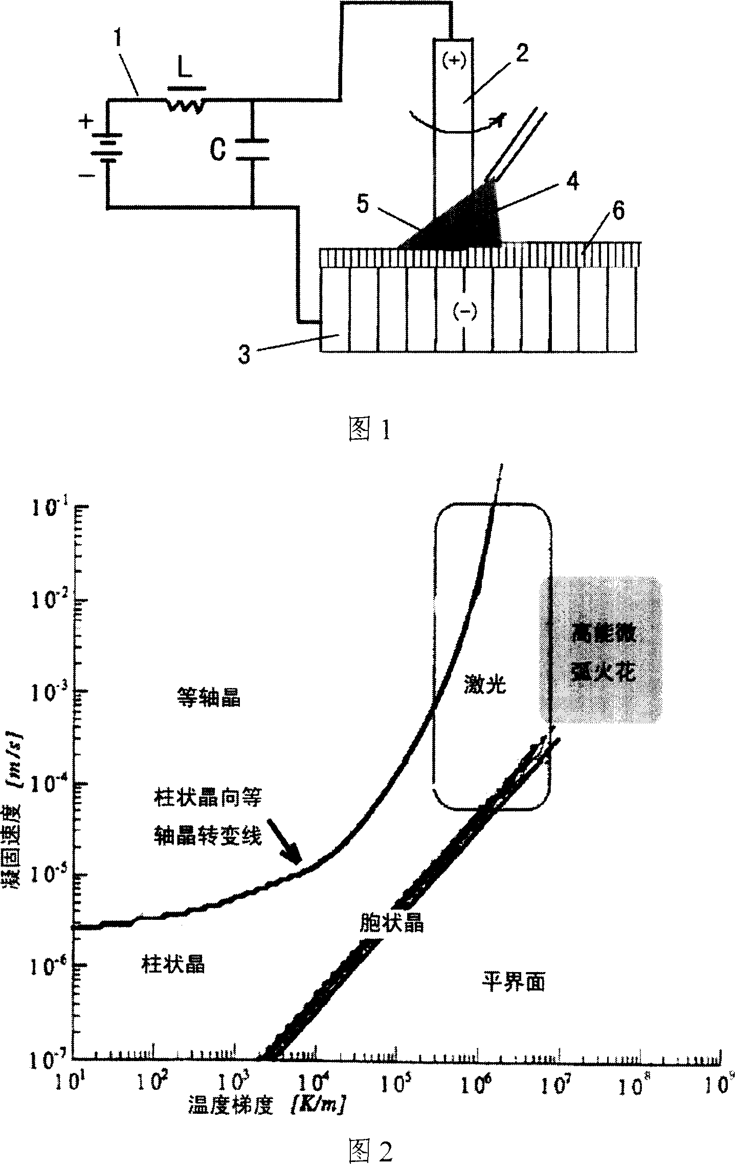
[0028]During deposition, the usual high-energy micro-arc spark deposition method is used: the repair material is IN738 rod (anode), with a diameter of 4mm, the substrate is directionally solidified DZ125 alloy (cathode), and epitaxial deposition is carried out on its preferred crystal plane (001) . As shown in Figure 1, under the action of a 1500W high-energy micro-arc spark generator 1 (in this embodiment, when depositing, the power is 960W, the frequency is 300Hz, and the anode speed is 3000...

Embodiment 2

[0030] The difference from Example 1 is:

[0031] The coating of single crystal nickel-based superalloy materials utilizes the ultra-high temperature gradient generated in the thin melt formed by high-energy micro-arc sparks, and the characteristics of epitaxial growth of the microstructure from the substrate when the thin melt solidifies. The nickel-based alloy material is used as the substrate, and high-energy micro-arc spark continuous deposition is performed on the preferred crystal plane (001).

[0032] During deposition, the usual high-energy micro-arc spark deposition method is adopted: the coating material is NiCrAlY rod as the anode, the diameter is 6mm, the substrate is a single crystal DD6 alloy (cathode), and epitaxial deposition is carried out on its preferred crystal plane (001) . Under the action of a 3000W high-energy micro-arc spark generator 1 (in this embodiment, during deposition, the power is 1920W, the frequency is 400Hz, and the anode speed is 1500 rpm)...

Embodiment 3

[0034] The difference from Example 1 is:

[0035] The repair of directionally solidified nickel-based superalloy materials uses the ultra-high temperature gradient generated in the thin melt formed by high-energy micro-arc sparks, and the characteristics of epitaxial growth of the microstructure from the substrate when the thin melt solidifies to directionally solidify nickel The base superalloy material is used as the substrate, and high-energy micro-arc spark continuous deposition is performed on the preferred crystal plane (001).

[0036] During deposition, the usual high-energy micro-arc spark deposition method is adopted: the coating material is DZ4 rod as the anode, the diameter is 4mm, the substrate is directionally solidified DZ4 alloy, and epitaxial deposition is carried out on its preferred crystal plane (001). A 1500W high-energy micro-arc spark generator is used. During deposition, the power is 200W, the frequency is 1000Hz, and the anode speed is 300 rpm. The tip ...


PUM

PropertyMeasurementUnit
thicknessaaaaaaaaaa

Abstract

The invention belongs to a preparation technique of the metal surface settled layer, in particular to a method for preparing the directional solidification column crystal or single crystal settled layer which grows on the extension of the surface of the directional solidification column crystal or single crystal high temperature alloy. The proposal of the invention solves the problem of repairing and coating of the directional solidification column crystal or single crystal high temperature alloy; and to gain a compact and flawless directional solidification column crystal or single crystal settled layer which is matched with the directional solidification column crystal or single crystal. The invention discloses an extension high power differential arc spark metal deposition technique. The invention has the advantages of wide process window achieved by the extension high power differential arc spark metal deposition technique, no heat damage to the ferronickel high temperature alloy, narrow heat influence area or no heat influence area, being capable of effectively avoiding the phenomenon of heat flaw of the ferronickel high temperature, no complicated devices such as vacuum room needed and no preheating needed.

Description

technical field [0001] The invention belongs to the preparation technology of a metal surface deposition layer, in particular to a method for preparing a directionally solidified columnar crystal or a single crystal deposition layer grown epitaxially on the surface of a directional solidified columnar crystal or a single crystal superalloy. Background technique [0002] Superalloys and their high-temperature protective coating systems play a pivotal role in aero-engines. At present, in advanced aero-engines, directionally solidified columnar crystals and even single crystals have gradually replaced traditional polycrystalline superalloys and are widely used. Due to the high price of directionally solidified columnar crystals and single crystal parts, in order to prolong these advanced superalloy parts as much as possible It is very important to research and develop superalloy directional solidification epitaxial deposition technology for repair and coating. [0003] The eme...

Claims


Application Information

Patent Timeline
Patent Type & Authority Applications(China)
IPC IPC(8): C23C4/00B23K9/04C23C4/06C23C4/131
Inventor 王茂才谢玉江王东生
Owner INST OF METAL RESEARCH - CHINESE ACAD OF SCI
Learn More