Microwave band-elimination filter based on tree shaped microstrip line construction

A technology of microstrip line and microwave strip, applied in waveguide-type devices, electrical components, circuits, etc., can solve the problems of insufficient stop-band attenuation, low production cost, narrow stop-band bandwidth, etc., and achieve cost and volume reduction, structure The effect of simple, large stopband bandwidth

Inactive Publication Date: 2009-02-04
CHINA JILIANG UNIV
View PDF0 Cites 2 Cited by
  • Summary
  • Abstract
  • Description
  • Claims
  • Application Information

AI Technical Summary

Problems solved by technology

[0004] The purpose of the present invention is to provide a kind of large stop band bandwidth, high stop band attenuation; Low cost, small size, easy to manufacture and integrate microwave band-stop filter based on tree-shaped microstrip line structure

Method used


Image

  • Microwave band-elimination filter based on tree shaped microstrip line construction
  • Microwave band-elimination filter based on tree shaped microstrip line construction
  • Microwave band-elimination filter based on tree shaped microstrip line construction

Examples


Embodiment 1

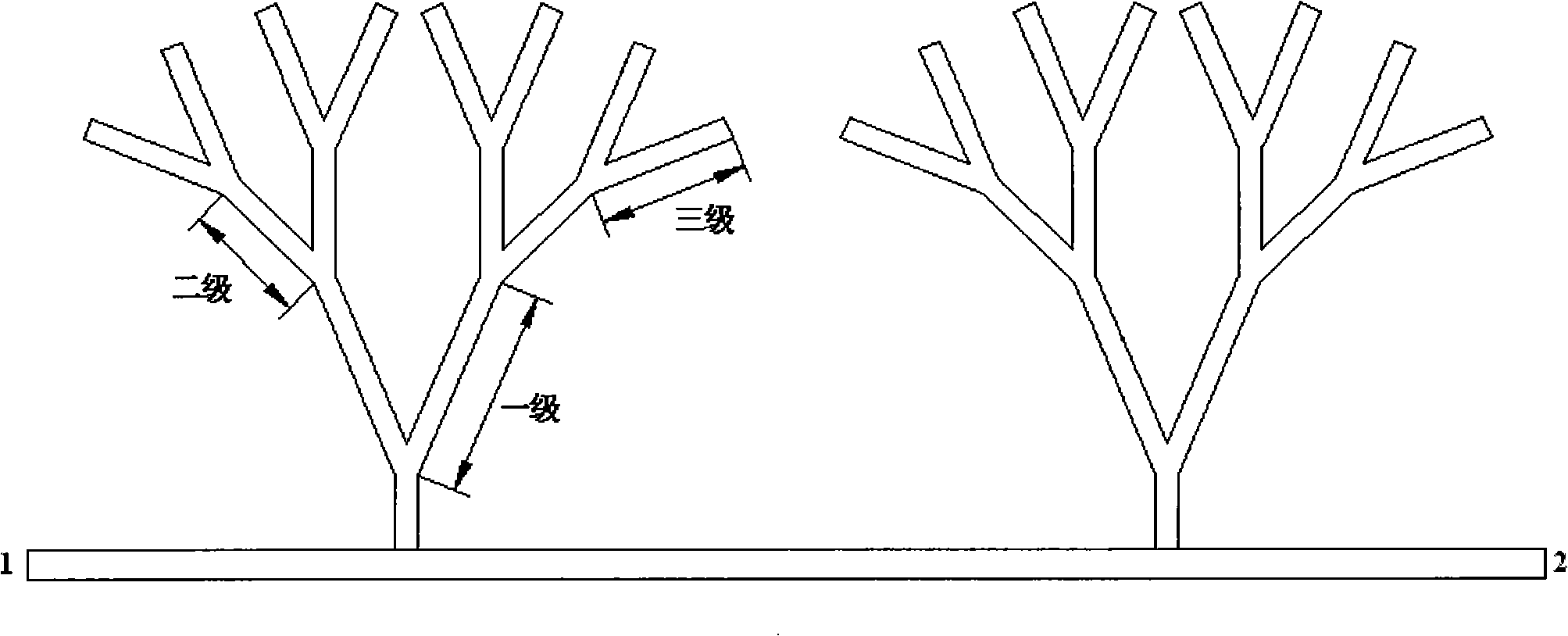
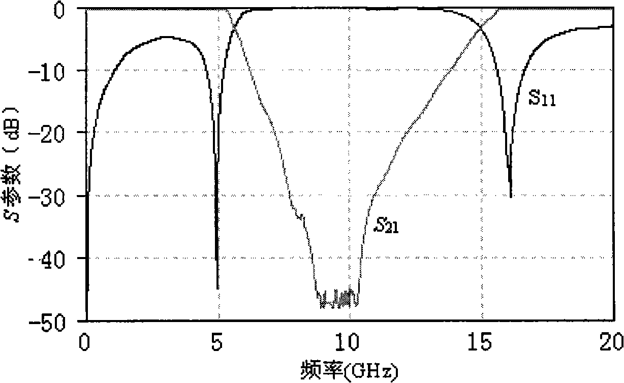
[0014] The structural size parameters of the microwave bandstop filter with tree-shaped microstrip line structure: 2 tree root microstrip lines, the length of the tree root microstrip line is 0.1mm, the opening angle of the V-shaped tree branch microstrip line is 30°, and the first-level V The length of the V-shaped branch microstrip line is 1.0mm, the length of the second-level V-shaped branch microstrip line is 0.5mm, the length of the third-level V-shaped branch microstrip line is 0.5mm, and the distance between the two root microstrip lines is 4.0mm. The line width is 0.1mm, the dielectric constant of the substrate is 2.0, and the thickness of the substrate is 0.2mm. figure 2 The performance curves of microwave band-rejection filters with two tree-shaped microstrip line structures are shown. The band-rejection filter has a stop-band bandwidth of up to 7GHz (from 6.5GHz to 13.5GHz), and the maximum stop-band attenuation is -48.7dB.

Embodiment 2

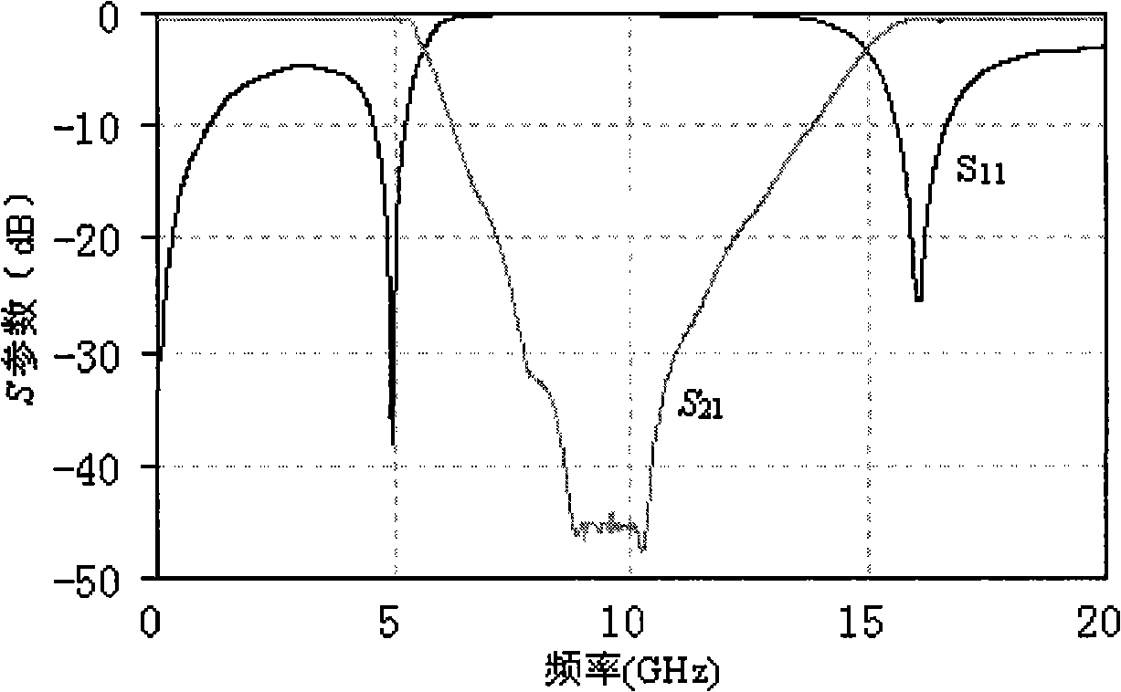
[0016] The structural size parameters of the microwave bandstop filter with tree-shaped microstrip line structure: 8 root microstrip lines, the length of the tree root microstrip line is 2.0mm, the opening angle of the V-shaped tree branch microstrip line is 90°, and the first-level V The length of the V-shaped branch microstrip line is 2.0mm, the length of the second-level V-shaped branch microstrip line is 1.0mm, the length of the third-level V-shaped branch microstrip line is 1.5mm, and the distance between the two root microstrip lines is 8.0mm. The line width is 0.6mm, the dielectric constant of the substrate is 16.0, and the thickness of the substrate is 3.0mm. image 3 The performance of the microwave band-rejection filter with 8 tree-shaped microstrip line structures is shown. The band-rejection filter has a stop-band bandwidth of 7 GHz (from 6.5 GHz to 13.5 GHz), and the maximum stop-band attenuation is -47.65 dB.


PUM

PropertyMeasurementUnit
Lengthaaaaaaaaaa
Line lengthaaaaaaaaaa
Widthaaaaaaaaaa

Abstract

The invention discloses a microwave band-stop filter based on a tree-shaped micro-strip line structure, wherein the matrix is equipped with microwave band-stop filter components; the microwave band-stop filter components are characterized in that a plurality of root micro-strip lines are disposed on a straight-through micro-strip transmission line; that Grade One V-shaped branch micro-strip lines are respectively arranged on the upper end of the plurality of root micro-strip lines; that Grade Two V-shaped branch micro-strip lines are respectively disposed on two top ends of each Grade One V-shaped branch micro-strip line; Grade Three V-shaped branch micro-strip lines are respectively arranged on two top ends of the Grade Two V-shaped branch micro-strip lines; and signal is sent into end 1 and out of end 2. The band-stop filter of tree-shaped microwave micro-strip line structure has advantages of large stop-band bandwidth, high stop-band attenuation, simple structure, easy assembly, light weight, saving materials, easy manufacturing and integration and greatly reducing the cost and size of the product.

Description

technical field [0001] The invention relates to a microwave band rejection filter based on a tree microstrip line structure. Background technique [0002] Now in many microwave systems, it is required that the signal propagates in it with as little loss as possible, and high suppression is required for the unwanted interference signal, so an ordinary band-pass filter can do the job, and for a certain interference If the signal is particularly strong, we need to take special measures to suppress it, and then use a band-stop filter. It is characterized by low band-pass loss and good band-stop suppression. [0003] Usually, the design of the band-stop filter is to connect the taps of the n cavities with a 50Ω transmission line with a wavelength λ of 1 / 4, 1 / 8 or other forms of impedance to control the size of the stop-band suppression through the coupling strength of the taps. The size of the passband and stopband isolation, the size of the passband insertion loss, and the num...

Claims


Application Information

Patent Timeline
IPC IPC(8): H01P1/203
Inventor 李九生李建蕊康岩龙
Owner CHINA JILIANG UNIV
Why Eureka
Try Eureka