
Motor control device for driving sliding frame of flat-knitting machine

A technology of tripod carriage and control device, which is applied in the direction of AC motor control, control system, optimized efficiency control at low load, etc., can solve problems such as shortening the service life, and achieve the effect of reducing load and avoiding appearance deterioration.

Inactive Publication Date: 2009-02-11
SHIMA SEIKI MFG LTD
View PDF2 Cites 1 Cited by
  • Summary
  • Abstract
  • Description
  • Claims
  • Application Information

AI Technical Summary

Problems solved by technology

Therefore, the load monitoring of the servo motor in this prior art is not for protection against shortened service life of the servo motor itself, but for protection of the grinding wheel driven by the servo motor

Method used


Image

  • Motor control device for driving sliding frame of flat-knitting machine
  • Motor control device for driving sliding frame of flat-knitting machine
  • Motor control device for driving sliding frame of flat-knitting machine

Examples


Embodiment

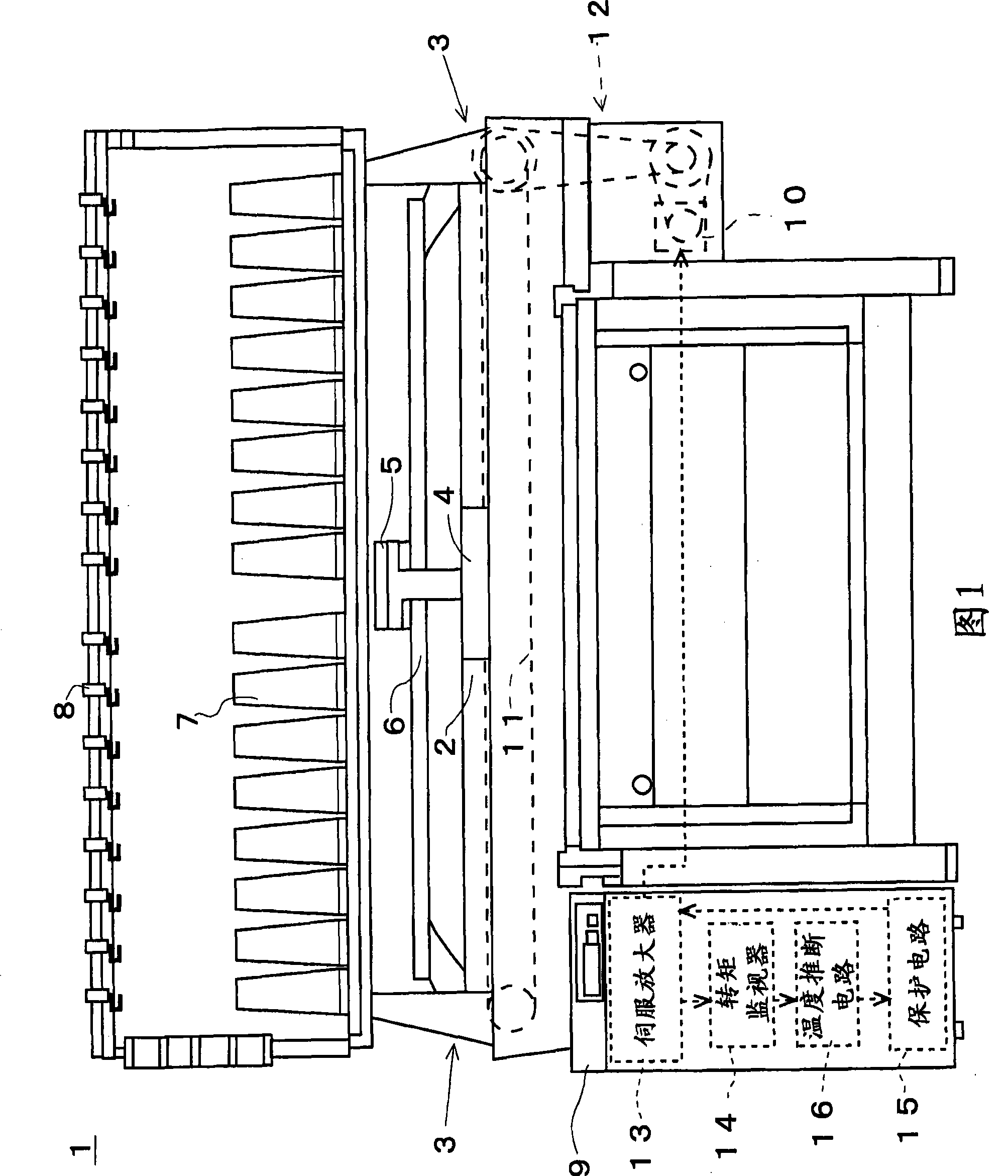
[0039] FIG. 1 shows a schematic external configuration of a flat knitting machine 1 according to an embodiment of the present invention. The flat knitting machine 1 has needle beds 2 in the front and rear, and faces the gap 3 in the middle. The carriages 4 are respectively provided on the front and rear needle beds 2 , and the carriages 4 are connected to the carriages 4 by the bridges 5 at the part of the tooth gap 3 . The carriage 4 is driven to reciprocate in the left-right direction in the drawing, that is, in the longitudinal direction of the needle bed 2 . A plurality of yarn guide rails 6 are erected above the tooth gap 3 . A yarn guide (not shown) as a yarn supplying member for supplying the knitting yarn to the gap 3 is movably supported on the yarn guide rail 6 . The bridge portion 5 is mounted on the guide rail 6 of the yarn guide, and can be driven by selecting a yarn guide from among a plurality of yarn guides. When performing plating knitting, etc., a pluralit...


PUM


Abstract

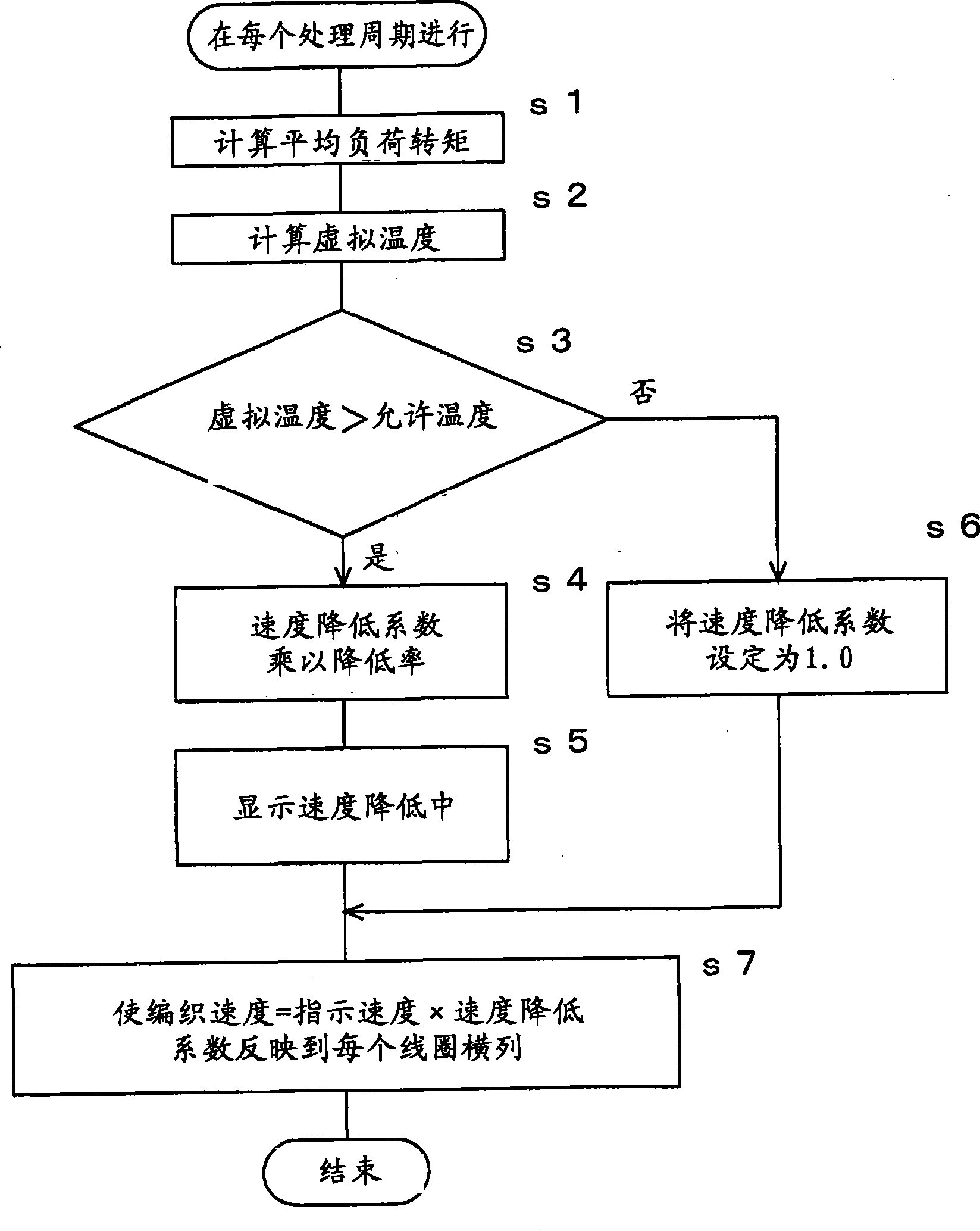
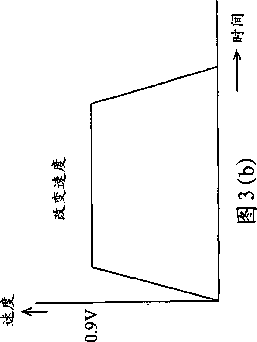
The invention provides a control device of an electric motor of the transverse machine tripod base sliding frame which can avoid reduced waving efficiency and the short service life caused by the heat even using the cheap electric motor with the load balance rating value by the usual motor under the maximum load weaving situation. In the stated time period, a torque monitor (14) monitors the load torque as the man electric motor (10). A temperature deducing circuit (16) calculates the temperature of the electric motor based on the average load torque of the monitoring result of the torque monitor (14). A protecting circuit (15) compares the virtual temperature to the predetermined allowed temperature. When the virtual temperature excesses the allowed temperature, the invention reduces the speed coefficient to 0.9 for the speed limitation. Under the condition that the virtual temperature is restored, the invention restores the speed coefficient to the original value 1.0.

Description

technical field [0001] The present invention relates to a control device for a carriage drive motor for a flat knitting machine that drives a carriage for knitting needles while moving along a needle bed. Background technique [0002] At present, for example, a general flat knitting knitting technique is described in the prior art section of Patent Document 1, and a carriage having a knitting cam for knitting can be reciprocated along and on a needle bed on which knitting needles are arranged. . As such a motor for driving a carriage, a servo motor, called a main motor, is used as a motive force for the knitting operation of the knitted fabric. [0003] On the flat knitting machine, the rated value of the motor for driving the carriage is selected so that it has sufficient output for the knitting pattern in which the knitting needle is used with the maximum load. Motors generally determine continuous ratings for continuous use and intermittent ratings for short-term use. ...

Claims


Application Information

Patent Timeline
IPC IPC(8): D04B15/36H02P23/00H02P23/02D04B15/96D04B15/99
Inventor 南方胜次
Owner SHIMA SEIKI MFG LTD
Learn More