
Magnetic lock

A magnetic lock and magnetic core technology, applied in the field of magnetic locks, can solve problems such as large power consumption, and achieve the effects of simple structure, easy implementation and low noise

Inactive Publication Date: 2009-02-11
游奕峰
View PDF0 Cites 1 Cited by
  • Summary
  • Abstract
  • Description
  • Claims
  • Application Information

AI Technical Summary

Problems solved by technology

[0003] In order to overcome the disadvantage of large power consumption of the existing magnetic lock, the present invention provides a magnetic lock, which not only has the advantages of light noise and no mechanical wear of the existing magnetic lock, but also overcomes the large power consumption of the existing magnetic lock. Compared with the power consumption of existing magnetic locks, it can save 70% to 85% of power consumption under the same tension and working voltage
[0005] The beneficial effect of the present invention is that while retaining the advantages of low noise and no mechanical wear of the existing magnetic lock, it also solves the disadvantage of large power consumption of the existing magnetic lock, and has a simple structure and is easy to implement

Method used


Image

  • Magnetic lock
  • Magnetic lock
  • Magnetic lock

Examples


Embodiment Construction

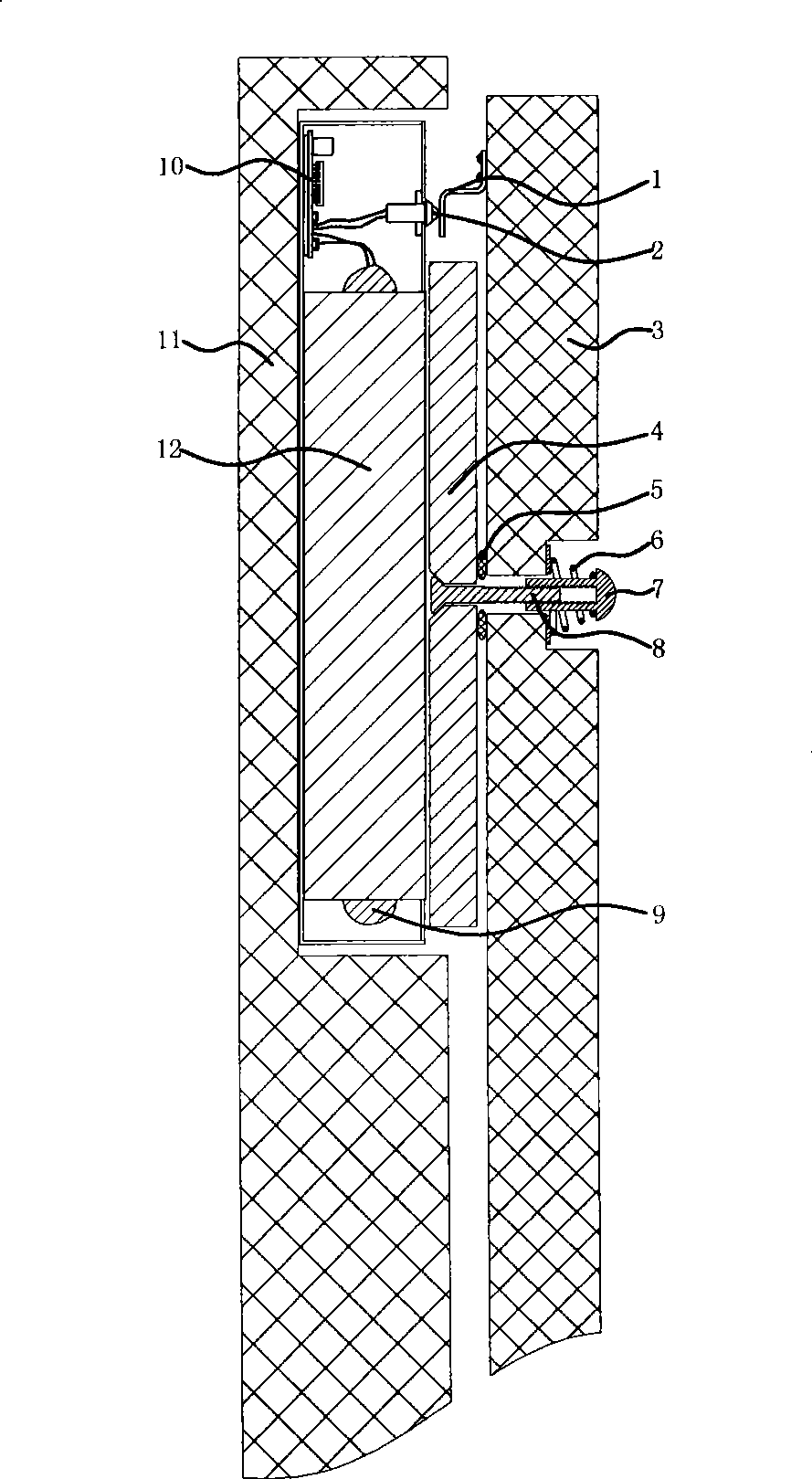
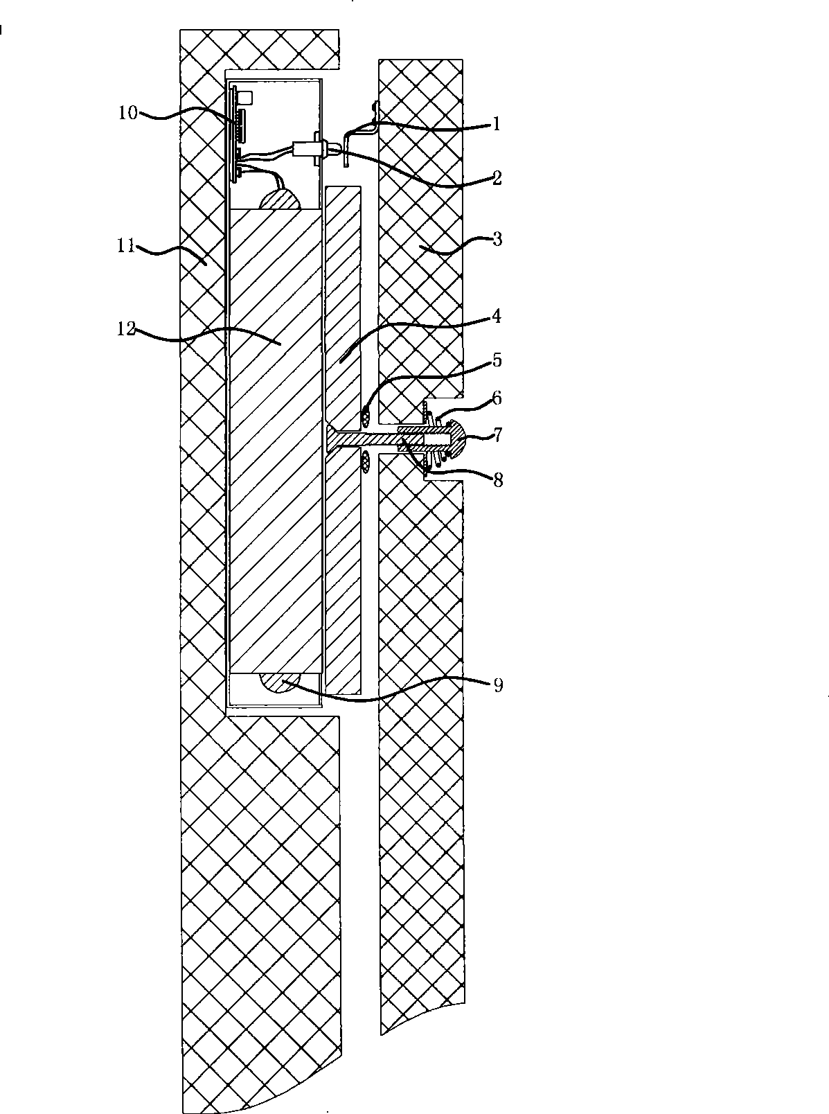
[0012] exist figure 1 Among them, the magnetic core (12), the coil (9), the circuit board (10), the suction plate positioning screw (8), the suction plate positioning nut (7), the suction plate (4), and the rubber pad (5) constitute the existing Features magnetic lock construction. Calculate the inventive features of this embodiment with the most common 270Kg pulling force in the market, operating voltage 12V, coil (9) current 280mA of magnetic core (12); present embodiment increases micro-displacement switch ( 2), switch contacts (1) and springs (6). The main body of the magnetic lock is installed on the door frame (11), and the suction plate (4) is installed on the door leaf (3). The main body of the magnetic lock and the suction plate (4) can be matched relatively when the door is closed. When the door leaf (3) is closed, the switch contact piece (1) resists the micro-displacement switch (2), so that the switch is closed.

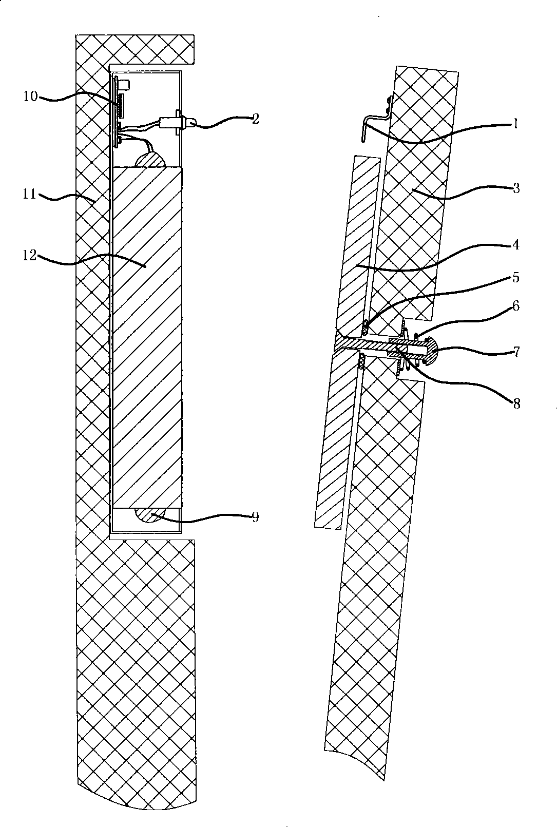
[0013] exist figure 2 , when the door leaf (3...


PUM


Abstract

The present invention relates to an energy-saving magnetic lock. One end of a magnetic lock body is provided with a micro displacement switch. At the position of closing the door, a micro displacement switch accessory of a door leaf drives the micro displacement switch at the magnetic lock body to close; after detecting a switch closing signal, a singlechip sends full current to a magnetic lock winding; and after two seconds, 70 percent to 85 percent of the current is reduced to keep the suction of the magnetic lock. When the door is pushed by illegal force or kicked by foot, the action of a buffer spring at a magnetic lock suction disc ensures that the high speed micro displacement switch gets an illegal kicking signal which is sent to the singlechip at the first moment; the singlechip controls and pushes a post circuit and sends the full current to the magnetic lock winding, the magnetic lock turns to maximum pull immediately for ten seconds; when the micro displacement switch is always under the close state, the circuit returns to the electricity-saving working state; and the problem of the high electricity consumption of the magnetic lock is solved. The energy-saving magnetic lock is simple in structure and is easy for implementation.

Description

1. Technical field [0001] The invention relates to a magnetic lock, especially capable of greatly reducing the power consumption of the magnetic lock. 2. Background technology [0002] The current known magnetic lock comprises a magnetic core, a coil, a circuit board and a suction plate. The magnetic lock has low noise and no mechanical wear, and has been widely used in various security places; because it is a power-off unlocking method, it is also the first choice for escape locks in public places. However, the biggest disadvantage of the magnetic lock is that it consumes a lot of power and needs long-term power supply to maintain the suction force; the working voltage of the magnetic lock on the market is generally 12V, and the existing magnetic lock needs to maintain 270mA (280Kg pulling force) or 500mA (24 hours a day) for a long time. 500Kg pulling force), whether it is unlocking or locking, the power consumption is the same. Although the magnetic lock is good, the pow...

Claims


Application Information

Patent Timeline
IPC IPC(8): E05B47/00
Inventor 游奕峰
Owner 游奕峰
Features
  • Generate Ideas
  • Intellectual Property
  • Life Sciences
  • Materials
  • Tech Scout
  • Unparalleled Data Quality
  • Higher Quality Content
  • 60% Fewer Hallucinations
Learn More