
Method and apparatus for engine control during auto-ignition combustion

一种内燃发动机、发动机的技术,应用在燃烧发动机、发动机控制、内燃活塞发动机等方向,能够解决控制系统稳态值滞后等问题

Active Publication Date: 2012-07-18
GM GLOBAL TECH OPERATIONS LLC
View PDF0 Cites 0 Cited by
  • Summary
  • Abstract
  • Description
  • Claims
  • Application Information

AI Technical Summary

Problems solved by technology

Several engine control parameters (including, eg, EGR, fuel pressure, and cam phasing) lag the steady-state value of the control system

Method used


Image

  • Method and apparatus for engine control during auto-ignition combustion
  • Method and apparatus for engine control during auto-ignition combustion
  • Method and apparatus for engine control during auto-ignition combustion

Examples


Embodiment Construction

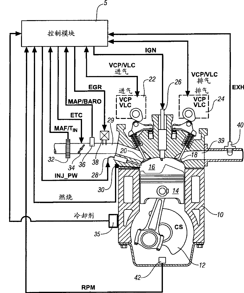
[0016] Referring now to the accompanying drawings, the description is only used to illustrate the purpose of the present invention, not to limit it. figure 1 A schematic diagram of an internal combustion engine 10 and an accessory control module 5 constructed according to an embodiment of the present invention is described.

[0017] The exemplary engine 10 includes a multi-cylinder direct injection four-stroke internal combustion engine having a reciprocating piston 14 slidable in a cylinder, the piston 14 defining a variable volume combustion chamber 16. Each piston is connected to a rotating crankshaft 12 ('CS'), and the linear reciprocating motion of the pistons is converted into rotary motion by the rotating crankshaft 12. The intake system provides intake air to the intake manifold, which introduces the air entering the intake passage 29 and distributes it to each combustion chamber 16. The air intake system includes airflow duct systems and devices for monitoring and contro...


PUM


Abstract

The invention relates to a method and a device for engine control during auto-ignition combustion.The invention comprises an engine system that is selectively operative in an auto-ignition combustion mode. A control module monitors engine operating states and control engine operation. A control subsystem controls engine operation based upon the monitored engine operating states. The control subsystem operates the engine in the auto-ignition combustion mode, and determines an effective temperature of the cylinder structure of the internal combustion engine based upon the engine operating conditions. An engine operating point is determined. A feed-forward control scheme is executed based upon the effective temperature of the cylinder structure and the engine operating point. The effective temperature of the cylinder structure is determined by monitoring engine power for an elapsed period of time.

Description

Technical field [0001] The present invention relates to an internal combustion engine, and more specifically to controlling its operation. Background technique [0002] The statements in this section only provide background information related to the present invention and may not constitute prior art. [0003] Internal combustion engines, especially automotive internal combustion engines, usually belong to one of two types, namely spark ignition engines and compression ignition engines. Conventional spark-ignited engines, such as gasoline engines, usually work by introducing a fuel / air mixture into a combustion cylinder, and then the fuel / air mixture is compressed during the compression stroke and ignited by a spark plug. Conventional compression ignition engines, such as diesel engines, usually work by introducing or injecting pressurized fuel into a combustion cylinder near the top dead center (TDC) of the compression stroke, which ignites during injection. The combustion of bo...

Claims


Application Information

Patent Timeline
Patent Type & Authority Patents(China)
IPC IPC(8): F02D43/00F02D41/04F02D41/40
CPCF02B17/005F02D41/3035F02D41/3064Y02T10/128Y02T10/12
Inventor R·B·拉斯克P·M·纳特
Owner GM GLOBAL TECH OPERATIONS LLC
Learn More