
Thermopile infrared detection device

A detection device, infrared technology, applied in the direction of measuring devices, electric radiation detectors, photometry, etc., can solve the problems of increased man-hours and high costs

Inactive Publication Date: 2009-02-11
NIPPON CERAMIC CO LTD
View PDF0 Cites 2 Cited by
  • Summary
  • Abstract
  • Description
  • Claims
  • Application Information

AI Technical Summary

Problems solved by technology

Therefore, there is an increase in man-hours, restrictions on the number of silicon plano-convex lenses installed in the evaporation furnace, and the influence of yield on the evaporation coating of the curved surface of the lens, and there is a problem in terms of cost.

Method used


Image

  • Thermopile infrared detection device
  • Thermopile infrared detection device
  • Thermopile infrared detection device

Examples


Embodiment 1

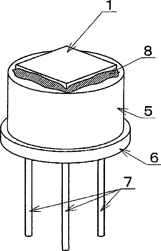
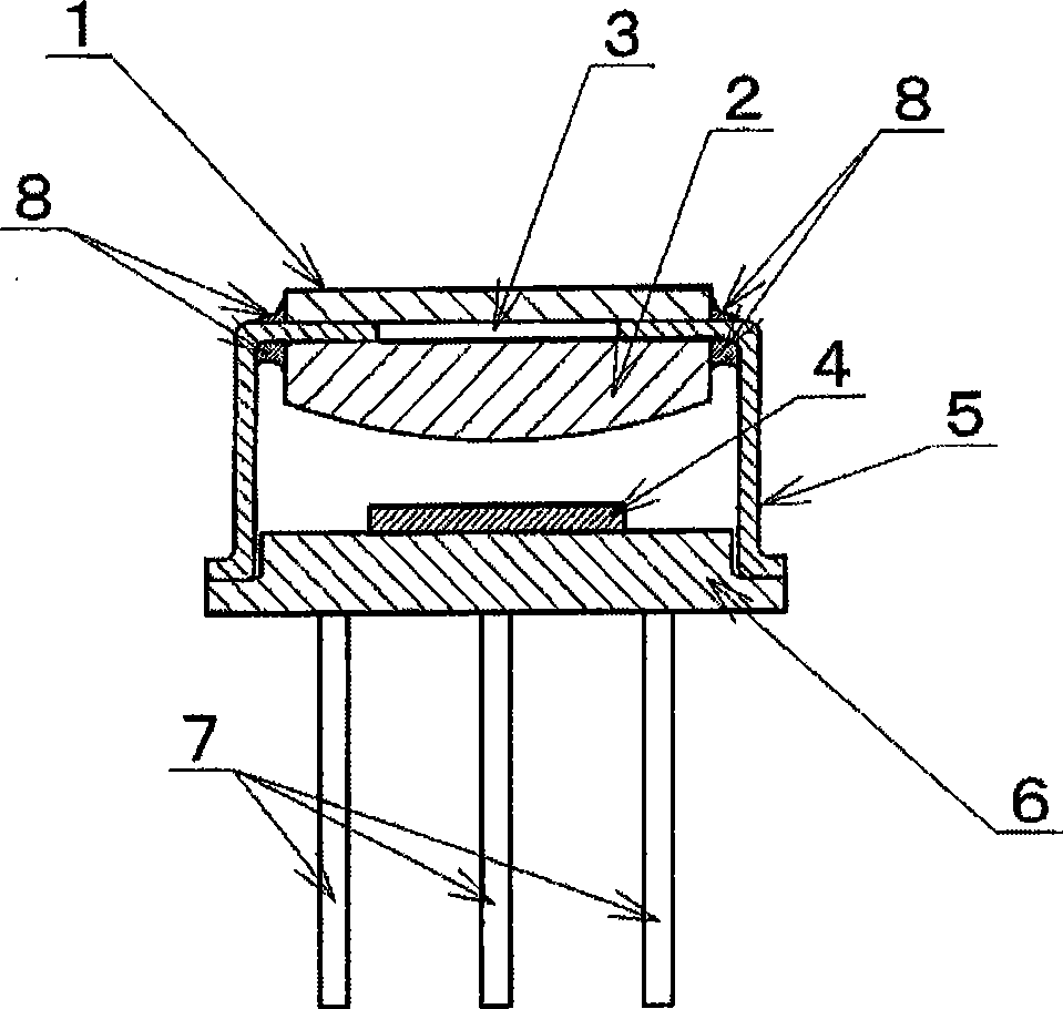
[0035] The present invention will be described in detail below using examples. figure 1 It is the most basic embodiment of the present invention, and shows the installation mode of the non-coated silicon plano-convex lens and the vapor-coated flat filter as the optical design part of the thermal pile sensor type infrared detection device. figure 2 Shows a schematic diagram of the internal cross-sectional structure.

[0036] In this embodiment, the structure is made such that the infrared incident amount of the thermal stack chip, which can measure the amount of radiated infrared rays of the object and detect the temperature of the object by receiving infrared rays, is projected by the object through optical design. The plano-convex lens made of silicon in the infrared detection area specified in the area, together with the metal can shell with infrared transmission window and the head with the lead terminal electrically connected to the thermal stack chip, is directed to pre...

Embodiment 2

[0043] Image 6 It shows the non-coated silicon plano-convex lens and the 5 μm non-coated silicon plano-convex lens used in Example 1 as the optical design part of the thermal-pile infrared detection device with the plane side and the convex side oppositely disposed. The way the coating plane filter is installed. Figure 7 Shows a schematic diagram of the internal cross-sectional structure.

[0044] Also can obtain and embodiment 1 in this embodiment Figure 5 The same infrared rays pass through the area.

Embodiment 3

[0046] Figure 8 The non-coated silicon plano-convex lens used in Example 1 and the non-coated silicon plano-convex lens used in Example 1 and the 5 μm coated flat filter by vapor deposition are shown as the optical design part of the thermal-pile infrared detection device with a front-to-back structure. Convex lens and 5μm planar filter are installed by evaporation coating. Figure 9 Shows a schematic diagram of the internal cross-sectional structure.

[0047] Also can obtain and embodiment 1 in this embodiment Figure 5 The same infrared rays pass through the area.


PUM


Abstract

As extraneous interference counter measure, selective vapor deposition coating with infrared permeation area is needed to apply to surface of a non-coating silicon plane-convex lens for a thermal reactor type infrared detecting device applied with optical design of the non-coating silicon plane-convex lens. But the working procedure of applying vapor deposition coating needs respectively to execute vapor deposition coating for lens, wherein problems of improved work hour, effected rate of finished products of vapor deposition coating on lens curve, and high cost are existed. The invention composed of thermal reactor type infrared detecting device applied with optical design of combination of the non-coating silicon plane-convex lens and a selective plane optical filter with infrared permeation area. Moreover, vapor deposition coating is applied integrally in slice state through plane optical filter as another component combination, not the non-coating silicon plane-convex lens, such that effectively cutting into arbitrary sizes can be carried out.

Description

technical field [0001] The present invention relates to a selective heat-pile infrared detection device with an infrared transmission area. Background technique [0002] The general thermal pile type infrared detection device used in the past has an optical structure composed of non-coated silicon as a base material such as silicon that does not have the selectivity of the infrared transmission region, or the surface of the silicon base material is deposited on the surface of the silicon base material. and other technologies apply a selective optical structure with an infrared ray transmission area of ​​the vapor deposition coating to provide. [0003] However, when using a thermal-pile infrared detection device to obtain the detection temperature, it is necessary to design the detection element and the optical system when detecting the object, and sometimes the optical design used on a general silicon or other flat filter cannot meet the requirements. Situation that requir...

Claims


Application Information

Patent Timeline
Patent Type & Authority Applications(China)
IPC IPC(8): G01J5/00G01J5/08
CPCG01J1/0238G01J3/108G01J5/0887G01J5/24
Inventor 川口浩二木村亲吾田中基树
Owner NIPPON CERAMIC CO LTD
Learn More