Optical membrane

A technology of optical film and convex lens, applied in optics, optical components, nonlinear optics, etc., can solve problems such as user discomfort, collapse, and inability to improve brightness at small viewing angles

Inactive Publication Date: 2009-02-11
PRODISC TECH INC
View PDF0 Cites 3 Cited by
  • Summary
  • Abstract
  • Description
  • Claims
  • Application Information

AI Technical Summary

Problems solved by technology

Because the attenuation range is very large, if the user watches the liquid crystal display at 45 degrees, the brightness will drop significantly, which will cause discomfort to the user
In addition, the light passing through the viewing angle of ±45 degrees to ±90 degrees will have a cut-off effect, so that when users watch the LCD at a large viewing angle, they will feel that its brightness suddenly becomes brighter

Method used


Image

  • Optical membrane
  • Optical membrane
  • Optical membrane

Examples


no. 1 example

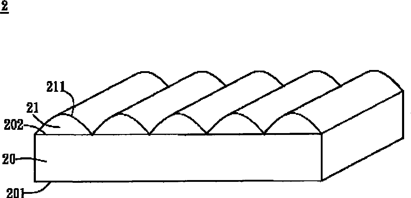
[0051] see image 3 As shown, an optical film 2 according to the first embodiment of the present invention includes a substrate 20 and a plurality of convex lens structures 21 . Wherein, the optical film 2 is an example of an optical film disposed in a backlight module of a liquid crystal display.

[0052] The substrate 20 has a first surface 201 and a second surface 202 , and the first surface 201 is opposite to the second surface 202 . Wherein, the material of the substrate 20 is transparent polyethylene terephthalate (PET) or polycarbonate.

[0053]The convex lens structures 21 are arranged in parallel and disposed on the second surface 202 of the substrate 20 . Each convex lens structure 21 has an arc surface 211, and the arc surface 211 conforms to a curved surface formula Ax 2 +By 2 +Cxy+Dx+Ey+F=0. It should be noted that in the surface formula, x and y are variables, and coefficients A, B, C, D, E, and F are constants, and the values ​​of coefficient A and coeffici...

no. 2 example

[0059] see Figure 7 As shown, an optical film 3 according to the second embodiment of the present invention includes a substrate 30 , a plurality of convex lens structures 31 and at least one triangular prism structure 32 . Wherein, the first surface 301 and the second surface 302 of the substrate 30 are disposed opposite to each other, and the material of the substrate 30 is the same as that of the substrate 20 in the first embodiment, so details will not be repeated here. The convex lens structures 31 are arranged adjacent to the triangular prism structure 32 and are arranged on the second surface 302, and the height H3 of the triangular prism structure 32 is smaller than the height H1 of the convex lens structure 31, so as to prevent the apex angle of the triangular prism structure 32 from being damaged. . It should be noted that the triangular prism structure 32 is used to increase the light-gathering effect of the optical film 3 , and the optical film 3 can adjust the q...

no. 3 example

[0061] see Figure 8 As shown, an optical film 4 according to the third embodiment of the present invention includes a substrate 40 , a plurality of convex lens structures 41 and a diffusion material 43 . The first surface 401 and the second surface 402 of the substrate 40 are disposed opposite to each other, and the convex lens structures 41 are disposed on the second surface 402. The material of the substrate 40 is the same as that of the substrate 20 in the first embodiment, and details are not repeated here. The diffusion material 43 can be disposed on the substrate 40 and / or the lenticular structure 41 . In this embodiment, the diffusion material 43 is disposed in the substrate 40 and the convex lens structure 41 in a doping manner, for example. Wherein, the diffusion material 43 is diffusion particles of titanium dioxide or silicon dioxide, or multilayer diffusion particles with different refractive indices.

[0062] like Figure 9 shown, with Figure 8 The differenc...


PUM


Abstract

The invention discloses an optical film which comprises a basal plate and a plurality of convex lens structures. The basal plate is provided with a first surface and a second surface, both of which are oppositely arranged. The convex lens structures are arranged on the second surface, each convex lens structure is provided with an arc surface, and the arc surface satisfies an arc surface formula: the sum of Ax<2>, By<2>, Cxy, Dx, Ey and F is 0, wherein, x and y are variables, and A, B, C, D, E and F are constants. The invention can increase the luminance of the optical film at a small visual angle, and also can reduce the light section effect of the optical film at a large visual angle.

Description

technical field [0001] The invention relates to an optical film, in particular to a film with the functions of diffusion and brightness enhancement. Background technique [0002] In order to improve the high visual quality of liquid crystal display, liquid crystal display must have the conditions of high brightness, wide viewing angle and uniform brightness, and the backlight module and its optical film are the key components to supply sufficient brightness and evenly distributed light . [0003] see figure 1 As shown, a conventional backlight module 1 includes a light source 10 , a light guide plate 11 and an optical film set 12 . Wherein, the backlight module 1 is a side-lit backlight module, and the light source 10 can be a CCFL or a plurality of LEDs. [0004] The optical film set 12 includes a lower diffusion film 121 , a first prism film 122 , a second prism film 123 and an upper diffusion film 124 . Wherein, the prism structures of the first prism film 122 and the...

Claims


Application Information

Patent Timeline
IPC IPC(8): G02B5/00G02F1/13357G02F1/1335
Inventor 蔡曜徽刘铭璿邱奕荣
Owner PRODISC TECH INC
Why Eureka
Try Eureka