
Self-adaptive standby power source self-throwing scheme for transforming plant lead-in circuit breaker

A technology for automatic switching of backup power supply and incoming line circuit breaker, which is applied in emergency power supply arrangements, circuit devices, electrical components, etc., which can solve the problems of poor device model versatility, maintenance device burden, and different action logic, so as to reduce the cost of transformation. , The effect of ensuring the reliability of power supply

Inactive Publication Date: 2009-02-11
QUJING POWER SUPPLY BUREAU YUNNAN POWER GRID CO LTD
View PDF2 Cites 36 Cited by
  • Summary
  • Abstract
  • Description
  • Claims
  • Application Information

AI Technical Summary

Problems solved by technology

[0003] Although the functions of the microcomputer self-injection devices currently in use are relatively complete, there are still common problems as follows: ①The action logic of each auto-injection manufacturer is different. Facing the same project, different manufacturers often have different processing methods, which is difficult for operators. Operators and maintenance personnel are burdened to maintain the device; ②The device model is not universal, even for the same manufacturer, different substation projects need to order different models of products; ③The device is poorly adaptable, and each manufacturer basically sets several fixed backups Investment mode, when the primary operation mode of the substation changes, it is necessary to switch among these fixed backup investment modes, but the manufacturer is not a power grid operation unit after all, and it is actually difficult to fully consider various operation modes

Method used


Image

  • Self-adaptive standby power source self-throwing scheme for transforming plant lead-in circuit breaker
  • Self-adaptive standby power source self-throwing scheme for transforming plant lead-in circuit breaker
  • Self-adaptive standby power source self-throwing scheme for transforming plant lead-in circuit breaker

Examples


Embodiment Construction

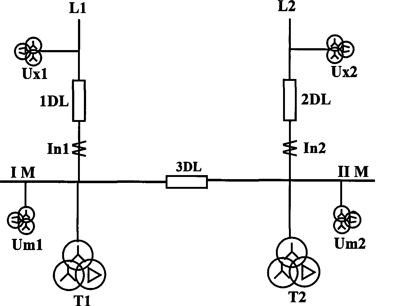
[0036] Through the analysis and comparison of the common bus connection methods of 110kV and below voltage levels used in the current power system, the objects of the circuit breakers with automatic switching function are classified into two categories: one is the power supply type, and the other is the intermediate connection type. Two types of backup methods are available figure 1 express.

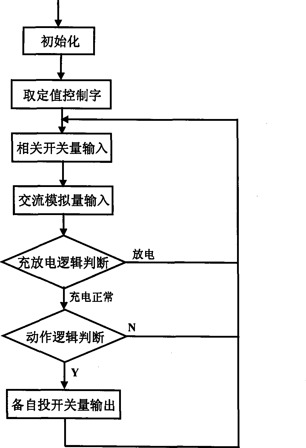
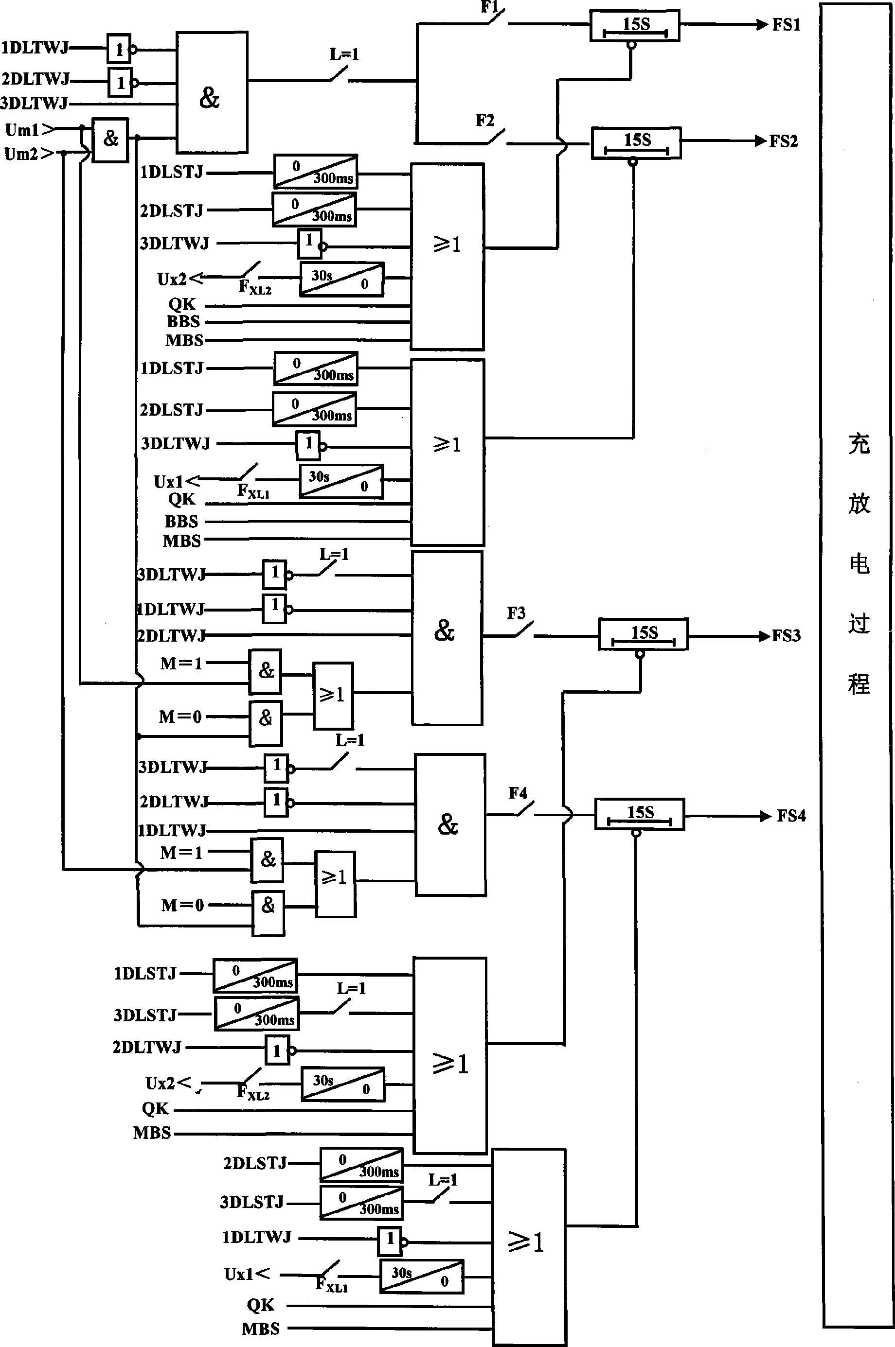
[0037] Combine below figure 1 ~5, the self-switching scheme of the adaptive backup power supply of the incoming circuit breaker provided by the present invention is described in detail.

[0038] Firstly, introduce several relevant control words in the program protection setting value setting. The line voltage check fixed value control word FxL is used to control whether the standby automatic switching logic checks the line voltage (Ux1, Ux2). When there is no bus voltage transformer on site, the standby automatic switching device will not check the line voltage; Inx (where x=1 or 2) i...


PUM


Abstract

The invention relates to a self-adaptive auto-switching scheme for standby power supply of an incoming circuit breaker of a transformer station. Breakers for standby auto-switching in the present power system are divided into a power type and an intermediate interconnection type. The self-adaptive auto-switching scheme for standby power supply is characterized in that self-adaptive standby switching function of standby auto-switching units can be achieved by adopting four work manners no matter what the main wiring manner of transformer station with a voltage level of 110 kV or less is; four standby auto-switching work manners can be selectively switched and the primary connection manner of a voltage transformer can be determined through protection value setting; and the state of an interconnection circuit breaker can be determined through value setting and external pressplate switching. The novel scheme can maximally reduce the alteration cost of the present equipment, and has application and popularization values. The standby self-switching unit adopting the scheme can self-adaptively operate under the different wiring manners and different operation manners without being operated by operators, thereby ensuring the power supply reliability.

Description

technical field [0001] The invention relates to the field of power system automation devices, in particular to a microcomputer incoming circuit breaker adaptive backup power supply self-injection scheme for power system 110kV and below substations. Background technique [0002] In order to improve the reliability of power supply and minimize the power outage time for users, the power system generally adopts the backup power automatic input device (hereinafter referred to as the standby automatic input device). Since the main wiring mode of the substation busbar is designed to fully consider the location of the substation in the power grid, investment costs, power supply reliability and other related factors, there are various main wiring modes of the 110kV and below substation busbars, and the common ones are single Bus section, double busbar, bridge connection and other methods; also due to factors such as investment cost and installation location, the primary wiring locati...

Claims


Application Information

Patent Timeline
IPC IPC(8): H02J9/06
Inventor 李国友孙建华姚捷黄文载徐飞匡华崔吉方杨俊宏阳家书
Owner QUJING POWER SUPPLY BUREAU YUNNAN POWER GRID CO LTD
Learn More