
Projection device and projection method

A technology of projection device and time-division method, which is applied in the direction of using projection device image reproducer, projection device, photography, etc., which can solve the problems of driving frequency influence and the inability to arbitrarily set the color wheel time period, etc.

Inactive Publication Date: 2009-02-11
CASIO COMPUTER CO LTD
View PDF0 Cites 12 Cited by
  • Summary
  • Abstract
  • Description
  • Claims
  • Application Information

AI Technical Summary

Problems solved by technology

[0014] However, even in the technology described in this patent document, the time period of each segment of the color wheel (occupancy angle of each segment on the color wheel) is affected by the driving frequency of the lamp
Therefore, the time period of each segment of the color wheel cannot be set arbitrarily

Method used


Image

  • Projection device and projection method
  • Projection device and projection method
  • Projection device and projection method

Examples


Embodiment Construction

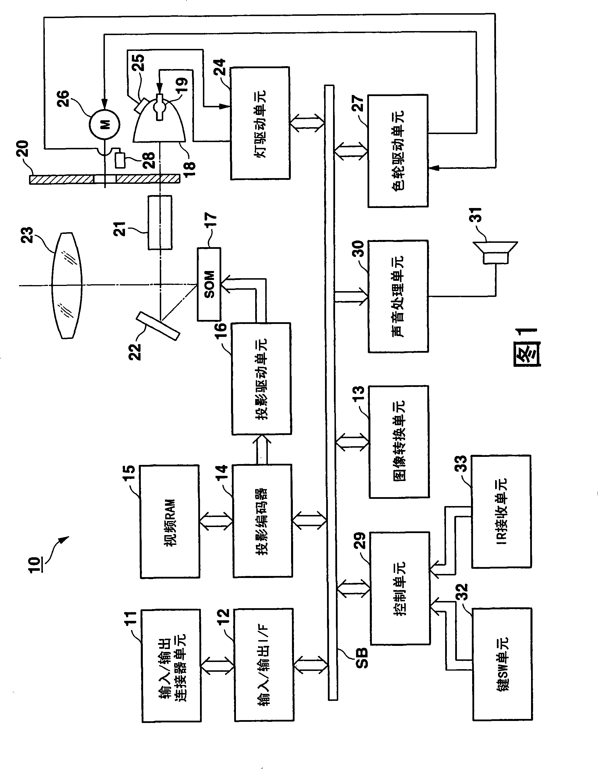
[0027] Embodiments of the projection apparatus and projection method according to the present invention will now be described with reference to the accompanying drawings. In the following description, the present invention is applied to a data projection apparatus 10 of a digital light display processing (DLP) (registered trademark) system.

[0028] FIG. 1 shows a circuit structure of a data projection apparatus 10 according to an embodiment of the present invention. Image signals of various standards input from the input / output connector unit 11 are supplied to the image conversion unit 13 via the input / output interface (I / F) 12 and the system bus SB, and converted into image signals having a predetermined format. The converted signal is provided to the projection encoder 14 .

[0029] The projection encoder 14 develops and stores the supplied image signal in the video RAM 15 , generates a video signal from the image signal stored in the video RAM 15 , and then outputs the v...


PUM


Abstract

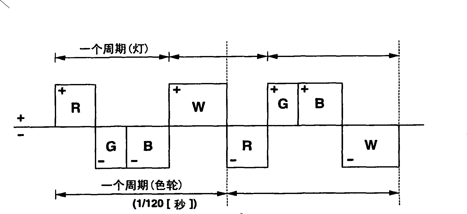
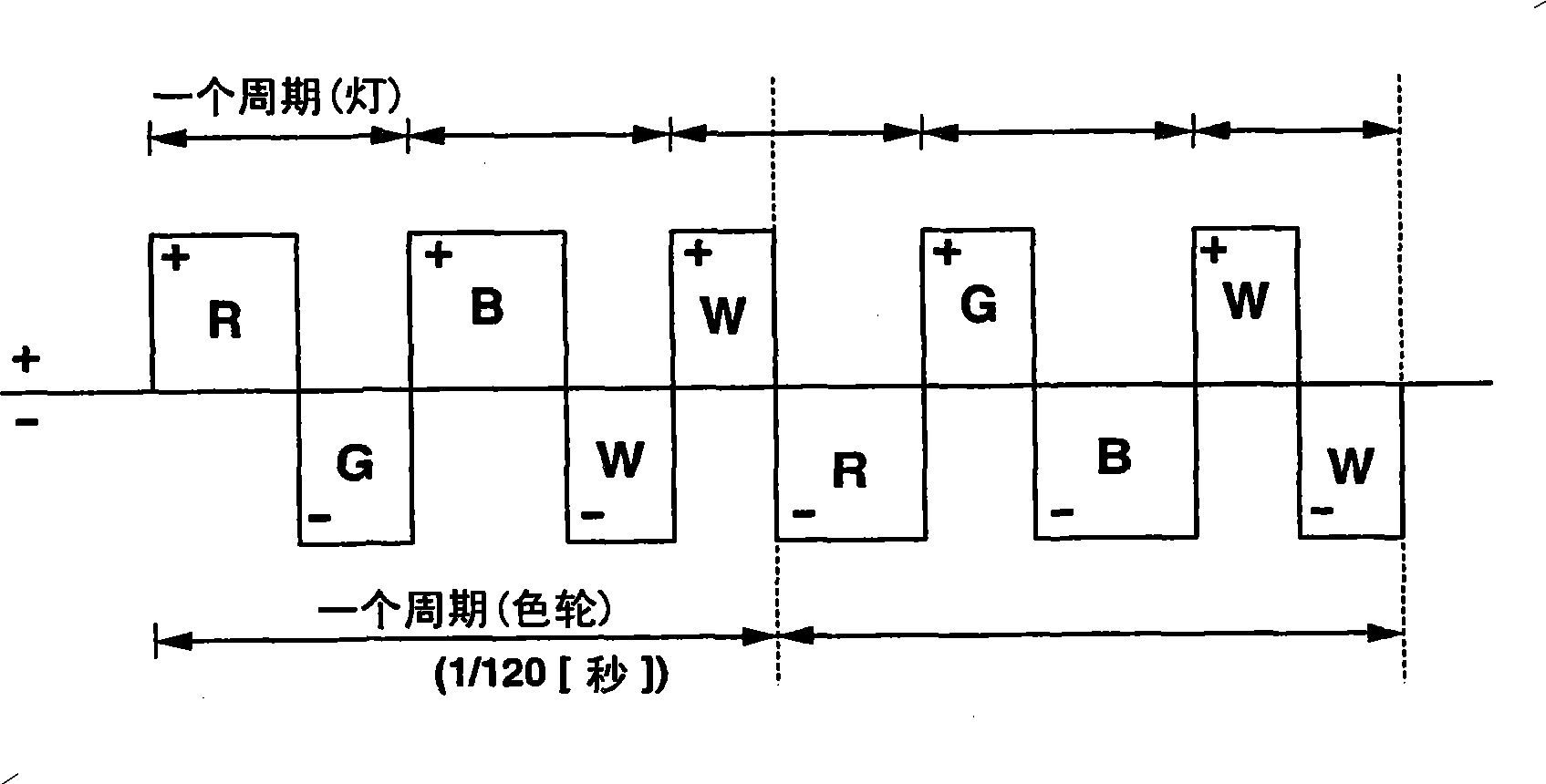
A projection device comprises a light source, a color wheel which is inserted into an optical path of the light source and in which a plurality of color segments are formed along a peripheral direction of the color wheel. The color segments are configured to transmit a plurality of wavelength band components in the white light in a time division manner during a rotation of the color wheel. A light source driving unit alternating-current discharges the light source at a period shorter than a rotation period of the color wheel while reverses a polarity at a timing to switch the segment of the color wheel inserted into the optical path.

Description

technical field [0001] The present invention relates to a projection apparatus and a projection method capable of projecting a color image by composing an image of primary color components in a time-division manner using a white light source and a color wheel. Background technique [0002] In a projection device of a Digital Light Display Processing (DLP) (registered trademark) system, light of each primary color component from a white light source is transmitted in a time-division manner via a component called a color wheel, which has at least a red (R ), green (G), and blue (B) primary color filters, and the primary color light is continuously reflected by the light modulation element in a time-division manner to display a monochromatic image. As a result, an optical image is constructed and projected, thereby projecting and displaying a color image. [0003] In this type of projection apparatus, a high-pressure mercury-vapor lamp that performs arc discharge is used as a ...

Claims


Application Information

Patent Timeline
Patent Type & Authority Applications(China)
IPC IPC(8): H04N5/74H04N9/31G03B21/00
CPCH04N9/3197G03B21/2053G03B21/204H04N9/3114H04N9/3155G03B21/14G03B21/20G03B33/08G03B21/40H04N9/31G02B5/20G02B27/18G02B26/00
Inventor 原口隆俊小久保孝志滨中秀雄
Owner CASIO COMPUTER CO LTD
Learn More