Pretensioning method for converting old simply supported beam bridge into continuous bridge

A technology of simply supported girder bridges and supported girder bridges, which is applied to bridges, bridge materials, bridge maintenance, etc., and can solve problems such as many expansion joints and frequent driving bumps

Inactive Publication Date: 2010-04-14
SOUTHEAST UNIV
View PDF2 Cites 0 Cited by
  • Summary
  • Abstract
  • Description
  • Claims
  • Application Information

AI Technical Summary

Problems solved by technology

After using this technology to connect the old simply supported girder bridge longitudinally into a continuous girder bridge, it overcomes the defects of multi-span long bridge deck expansion joints and frequent driving bumps.

Method used


Image

  • Pretensioning method for converting old simply supported beam bridge into continuous bridge
  • Pretensioning method for converting old simply supported beam bridge into continuous bridge
  • Pretensioning method for converting old simply supported beam bridge into continuous bridge

Examples


specific Embodiment approach

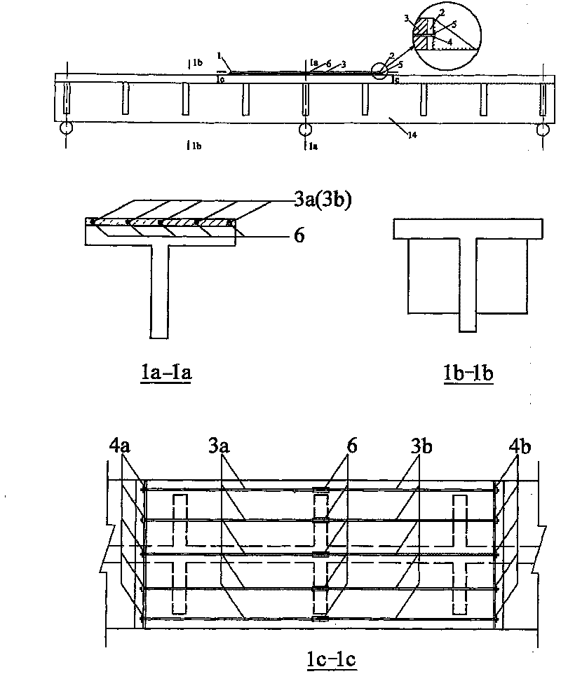
[0028] A pretensioning method for converting old simply supported girder bridges into continuous girder bridges:

[0029] a. Embed vertically placed horizontal first steel plate 1 on one side of the end that needs to be connected in the longitudinal direction of old simply supported T-beam 14, and embed vertically placed horizontally second steel plate 2 on the other side, and lay connection pre-installation on the steel plate. The position of the stress tendons 3 is drilled in advance, and the size of the holes can pass through the prestress tendons 3,

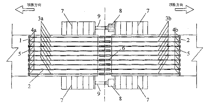
[0030] B. in the hole 4a of the first steel plate, penetrate the prestressed tendon 3a, also penetrate the prestressed tendon 3b in the hole 4b of the second steel plate, will be positioned at the prestressed tendon outside the area between the first steel plate and the second steel plate One end of the tendon is anchored with a heading anchor 5, and the other end of the prestressed tendon passing through the first steel plat...


PUM


Abstract

Disclosed is a pretensioning method for converting an old simply supported girder bridge into a continuous girder bridge, including the following steps: pre-burying a first steel plate and a second steel plate respectively on both to-be-connected sides of the old simply supported T girder, and drilling holes on the steel plates in advance corresponding to the position paved with connecting prestressing tendons; wherein, the size of holes is big enough for the prestressing tendons to run through; threading the prestressing tendons in the holes of the steel plates, anchoring one end of each prestressing tendon, and connecting the other ends of the prestressing tendons which thread through the first steel plate and the second steel plate through a connector; wherein, the holes of the two prestressing tendons on the first steel plate and the second steel plate are opposite and the prestressing tendons are placed inside the holes; screwing down the connector and tensioning the prestressingtendons; propping and pushing the girder outwards through a jack; widening the to-be-connected ends of the T girders, arranging a lateral clapboard between the connected ends of the to-be-connected Tgirders, and casting concrete on the connected ends and the bridge deck; and removing the jack after the newly cast concrete reaches the designed tension. In this way, prestress can be transferred tothe negative moment area of the reinforced concrete T girder through the old and the new concrete interfaces.

Description

technical field [0001] The invention relates to a method for longitudinally forming continuous girders from old simply supported girder bridges by applying prestress, in particular to a pre-tensioning method for transforming old simply supported girder bridges into continuous girder bridges by changing the structural system for reinforcement. Background technique [0002] The simply supported reinforced concrete T-beam bridge is a bridge structure widely used in my country. After years of operation, under the influence of various external factors, the bearing capacity and stiffness of reinforced concrete T-beams can no longer meet the requirements of modern transportation. In recent years, the commonly used methods for strengthening old simply supported girder bridges include pasting steel plate method and pasting carbon fiber cloth method. Although the external reinforcement method is simple in construction, it has two major disadvantages: [0003] 1. The high-strength per...

Claims


Application Information

Patent Timeline
Patent Type & Authority Patents(China)
IPC IPC(8): E01D22/00E01D101/28
Inventor 王文炜翁昌年李果
Owner SOUTHEAST UNIV
Why Eureka
Try Eureka