Vehicle fuel oil evaporation control system and method thereof
A control system and control method technology, applied in the direction of charging system, adding non-fuel substances to fuel, engine components, etc., can solve the problem of unsolved fuel vapor control and recycling, technical solution applicability limitations, technical solution imperfections, etc. problems, to achieve and control the pollution of the environment, the structure is simple, and the design is reasonable
- Summary
- Abstract
- Description
- Claims
- Application Information
AI Technical Summary
Problems solved by technology
Method used
Image

Examples
Embodiment 1
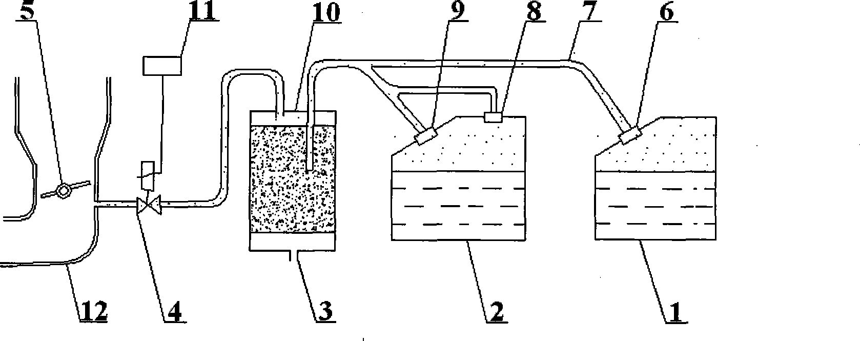
[0030] The fuel vapor pipe 7 communicates with the methanol fuel tank 2 through the methanol tank gravity valve 8 and the methanol tank gravity valve 9; the fuel vapor pipe 7 communicates with the gasoline fuel tank 2 through the gasoline tank gravity valve 6 .
[0031] This embodiment has solved under what condition, the problem that fuel vapor begins to flow to gac canister 10, namely at higher temperature, make the pressure of the fuel vapor of gasoline fuel tank 1 and methanol fuel tank 2 exceed methanol tank gravity valve 8, The setting value of methanol tank gravity valve 9 and gasoline tank gravity valve 6, these gravity valves can be opened automatically, and high-pressure fuel vapor flows to activated carbon canister 10 through fuel vapor pipe 7. Therefore, the opening pressure of the above-mentioned gravity valve can be set according to the needs of different fuels and different vehicle models.
Embodiment 2
[0033] The pipeline between the activated carbon canister 10 and the engine intake pipe 12 of the vehicle fuel evaporation control system is the canister output pipeline 13, and the canister solenoid valve 4 is arranged on the pipeline, and the canister solenoid valve 4 communicates with the engine through the signal line. The electronic control unit 11 (ECU) is connected, and the engine electronic control unit 11 (ECU) sends an open or close signal to the canister solenoid valve 4 .
[0034] The setting of the above structure makes the fuel evaporation control system coordinate with the overall working state of the engine, and its work is more reliable, its performance is better, and its efficiency is higher. Whether the canister output pipeline 13 is open or not is controlled by the ECU of the engine and implemented by the opening and closing of the canister solenoid valve 4 .
Embodiment 3
[0036]The activated carbon canister 10 is provided with a canister atmospheric through hole 3 .
[0037] This structure enables the adsorption and recovery of vapor to form different circuits according to different conditions:
[0038] If the canister solenoid valve 4 is closed and each gravity valve is opened, the high-pressure oil vapor is filtered and the clean gas is discharged from the canister atmospheric hole 3;
[0039] If the canister solenoid valve 4 is opened and the gravity valves are closed, the air will be sucked from the atmospheric hole 3 of the canister, and the fuel adsorbed on the activated carbon particles will be washed away, and will be sucked into the engine through the canister output pipeline 13 in the form of oil and gas. combustion in the cylinder;
[0040] If the canister electromagnetic valve 4 and each gravity valve are both open, the gas flow direction at the canister atmospheric hole 3 is determined according to the difference in the flow rate ...
PUM
 Abstract
Description
Claims
Application Information
 - R&D
- Intellectual Property
- Life Sciences
- Materials
- Tech Scout
- Unparalleled Data Quality
- Higher Quality Content
- 60% Fewer Hallucinations
Browse by: Latest US Patents, China's latest patents, Technical Efficacy Thesaurus, Application Domain, Technology Topic, Popular Technical Reports.
© 2025 PatSnap. All rights reserved.Legal|Privacy policy|Modern Slavery Act Transparency Statement|Sitemap|About US| Contact US: help@patsnap.com