
Mine safety wireless location system and its laying method based on ZigBee and RFID

A wireless positioning system and safe technology, applied in the field of wireless network communication, can solve the problems of short working time, low positioning accuracy, and inconvenient portability, and achieve the effect of long working time, low cost, and easy portability

Inactive Publication Date: 2009-02-18
HARBIN INST OF TECH
View PDF1 Cites 37 Cited by
  • Summary
  • Abstract
  • Description
  • Claims
  • Application Information

AI Technical Summary

Problems solved by technology

[0004] The present invention provides a ZigBee-based and RFID-based mine safety wireless positioning system and its Layout method

Method used


Image

  • Mine safety wireless location system and its laying method based on ZigBee and RFID

Examples


specific Embodiment approach 1

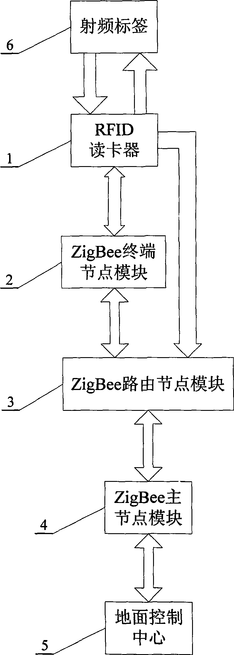
[0015] Specific implementation mode one: see figure 1 , this embodiment consists of the following units:

[0016] The RFID card reader 1 is used to radiate power to the radio frequency tag 6 in the coverage area through the antenna and receive the tag data from the radio frequency tag 6, and send the received tag data to the ZigBee terminal node module 2 or ZigBee router through the serial port (RS232) Node module 3, and receive control data from ZigBee terminal node module 2;

[0017] ZigBee terminal node module 2 is used to send the tag data from RFID card reader 1 to ZigBee routing node 3 module, and the control data from ZigBee routing node module 3 is sent to RFID card reader 1 through serial port (RS232);

[0018] ZigBee routing node module 3 is used to send the tag data from RFID card reader 1 or ZigBee terminal node module 2 to ZigBee master node module 4, and send the control data from ZigBee master node module 4 to ZigBee terminal node module 2 Or send it to RFID c...

specific Embodiment approach 2

[0024] Specific embodiment two: This embodiment further defines on the basis of specific embodiment one that the ZigBee terminal node module 2, the ZigBee routing node module 3 and the ZigBee master node module 4 are all provided with a watchdog module inside.

[0025] Due to the complex environment in the roadway, the deployed ZigBee terminal node module 2, ZigBee routing node module 3 and ZigBee master node module 4 are prone to software failures. The watchdog module can automatically restart in a short time to realize the function of network self-recovery .

specific Embodiment approach 3

[0026] Embodiment 3: On the basis of Embodiment 1, this embodiment further defines that every two adjacent ZigBee routing node modules 3 in the roadway are set at a distance of less than 45-50 meters.

[0027] The effective coverage of ZigBee is about 100 meters. Once a ZigBee module fails in the complex environment under the mine, two ZigBee modules separated by a ZigBee module in the middle can also be automatically searched and connected, which improves the system. safety and stability.


PUM


Abstract

A mine safety wireless positioning system based on the ZigBee and RFID and a layout method thereof is disclosed. The invention relates to a wireless network positioning device constructed in a mine using the ZigBee technology and the RFID technology and a layout method thereof, in order to solve the problems of shorter work time, lower positioning precision, higher cost and inconvenient carrying existing in the prior mine positioning system. An RFID card reader transmits the received label data to a ZigBee terminal node module or a ZigBee routing node module, and receives the control data from the ZigBee terminal node module or a ZigBee routing node module. The ZigBee terminal node module and the ZigBee routing node module transmit the label data to a ZigBee main module. The ZigBee main node module transmits label data to a ground control center. The ground control center comprehensively analyzes the label data and the personnel information and node position information in a center data-base and writes the position information into the center data-base.

Description

technical field [0001] The invention relates to a wireless network positioning device and a laying method thereof in a mine by using ZigBee technology and an RFID card reader, belonging to the field of wireless network communication. Background technique [0002] Mine mining, as a heavy industry with frequent safety accidents, has high requirements for safety supervision and management systems. The use of wireless communication positioning systems to monitor underground personnel in real time will greatly enhance the safety of underground operations. At present, in some large state-owned coal mines in my country, the purpose of distributing mobile phones with GPS (Global Positioning System, Global Positioning System) function to each miner or laying communication cables in underground tunnels is to realize personnel positioning. These technologies have considerable limitations. First of all, GPS mobile phones consume a lot of power. Even if the mobile phone battery is fully ...

Claims


Application Information

Patent Timeline
IPC IPC(8): H04L12/28G06K17/00
Inventor 吴群董建丁同禹王然赵铁刚
Owner HARBIN INST OF TECH
Learn More