Scintillation element, scintillation array and method for producing the same

A scintillation array and element technology, applied in the field of scintillation elements and scintillation arrays, can solve the problems of high duration, long reconstruction image, etc., and achieve the effects of increasing light output, reducing afterglow, and simple preparation method

Inactive Publication Date: 2009-02-18
KONINKLIJKE PHILIPS ELECTRONICS NV
View PDF0 Cites 12 Cited by
  • Summary
  • Abstract
  • Description
  • Claims
  • Application Information

AI Technical Summary

Problems solved by technology

GOS has the advantages of high light yield and absorption efficiency, but generally shows an afterglow signal after irradiat...

Method used


Image

  • Scintillation element, scintillation array and method for producing the same
  • Scintillation element, scintillation array and method for producing the same
  • Scintillation element, scintillation array and method for producing the same

Examples


Embodiment Construction

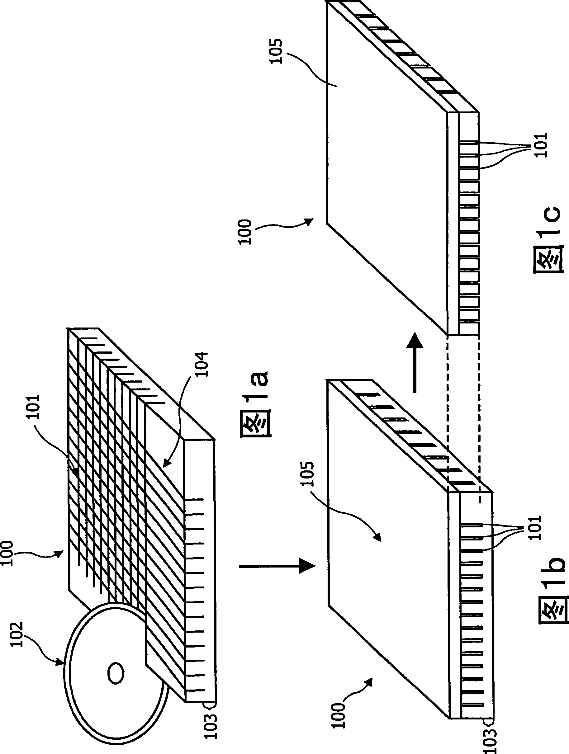
[0045] Figure 1 schematically shows the scintillation array, specifically the structured and coated Gd 2 o 2 Preparation method of S(GOS) scintillation array. GOS powder is used as raw material, which is preferably doped with praseodymium (Pr) and cerium (Ce). Then, lithium fluoride (LiF) is added in a small amount, eg at a relatively low concentration. Typically, Gd 2 o 2 The Pr concentration in S is in the range of 100-2000 wtppm of GOS (most preferably between 500-1000 wtppm), while the Ce concentration is based on Gd 2 o 2 S is between 0.1-100 ppm by weight and is selected according to the Eu content of GOS, which is most preferably based on Gd 2 o 2 S is 1 weight ppm or less. The flux LiF has a Gd based 2 o 2 S is at a concentration of 0.001-1 wt.%, most preferably 0.02 wt.%. when Ce 3+ With the addition of cerium to compensate for the effect of europium and the addition of Pr as an ion associated with the scintillation process, LiF is added as a sintering aid...


PUM


Abstract

A scintillation element comprises a scintillation material, and a reflective layer, wherein the reflective layer is formed as an intrinsic part of the scintillation material. Preferably, a plurality of scintillation elements may be arranged to form a scintillation array. A method for producing a scintillation element comprises providing a scintillation material, and producing a reflective layer at the scintillation material by exposing the scintillation material to physical and/or chemical conditions in such a way that the reflective layer is formed out of a part of the scintillation material.

Description

technical field [0001] The present invention relates to a scintillation element, a scintillation array, a preparation method of the scintillation element and a preparation method of the scintillation array, in particular, to a scintillation element and a scintillation array which can be used in the field of computed tomography (CT). Background technique [0002] In computed tomography (CT), the fluorescent ceramic Gd 2 o 2 S:Pr,Ce(GOS) was used as scintillator material to convert x-ray photons to visible light. GOS has the advantage of high light yield and absorption efficiency, but generally shows an afterglow signal after irradiation. This afterglow has a signaling effect which is so high and long lasting that the reconstructed image suffers from severe artefacts. Proper post-treatment of ceramic pieces, for example, by annealing in air for several hours, can reduce such afterglow. Besides afterglow, the issue of light yield is the most important for CT applications. ...

Claims


Application Information

Patent Timeline
IPC IPC(8): G01T1/20G01T1/202
CPCG01T1/2002G01T1/202
Inventor G·蔡特勒H·施赖讷马赫尔C·R·龙达N·康拉茨
Owner KONINKLIJKE PHILIPS ELECTRONICS NV
Why Eureka
Try Eureka