Method of and apparatus for monitoring flow of lubricant vapor forming lubricant coatings of magnetic disks

A technology of lubricant and steam, which is applied in the field of monitoring the mass flow rate of lubricant steam flowing through the steam to the vacuum chamber, and can solve the problems of interruption, waste and inefficiency of manufacturing arrangements

Inactive Publication Date: 2009-02-25
INTERVIDEO
View PDF1 Cites 3 Cited by
  • Summary
  • Abstract
  • Description
  • Claims
  • Application Information

AI Technical Summary

Problems solved by technology

Due to the finite lifetime of piezoelectric crystals, the crystals must be replaced relatively frequently, which would lead to disruptions in the operation of the manufacturing arrangements for said crystal separation
Such interruptions are inefficient and wasteful

Method used


Image

  • Method of and apparatus for monitoring flow of lubricant vapor forming lubricant coatings of magnetic disks
  • Method of and apparatus for monitoring flow of lubricant vapor forming lubricant coatings of magnetic disks
  • Method of and apparatus for monitoring flow of lubricant vapor forming lubricant coatings of magnetic disks

Examples


Embodiment Construction

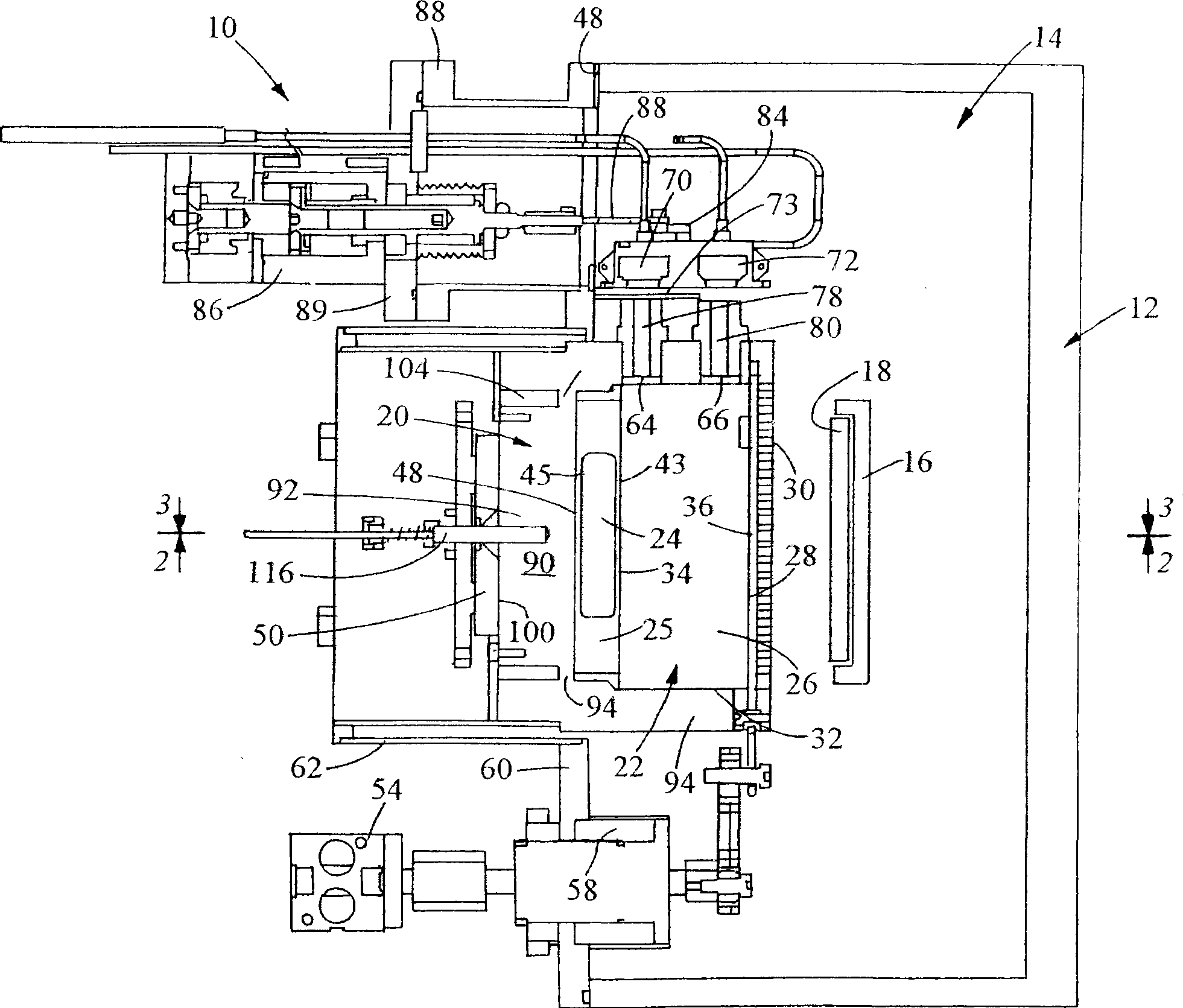
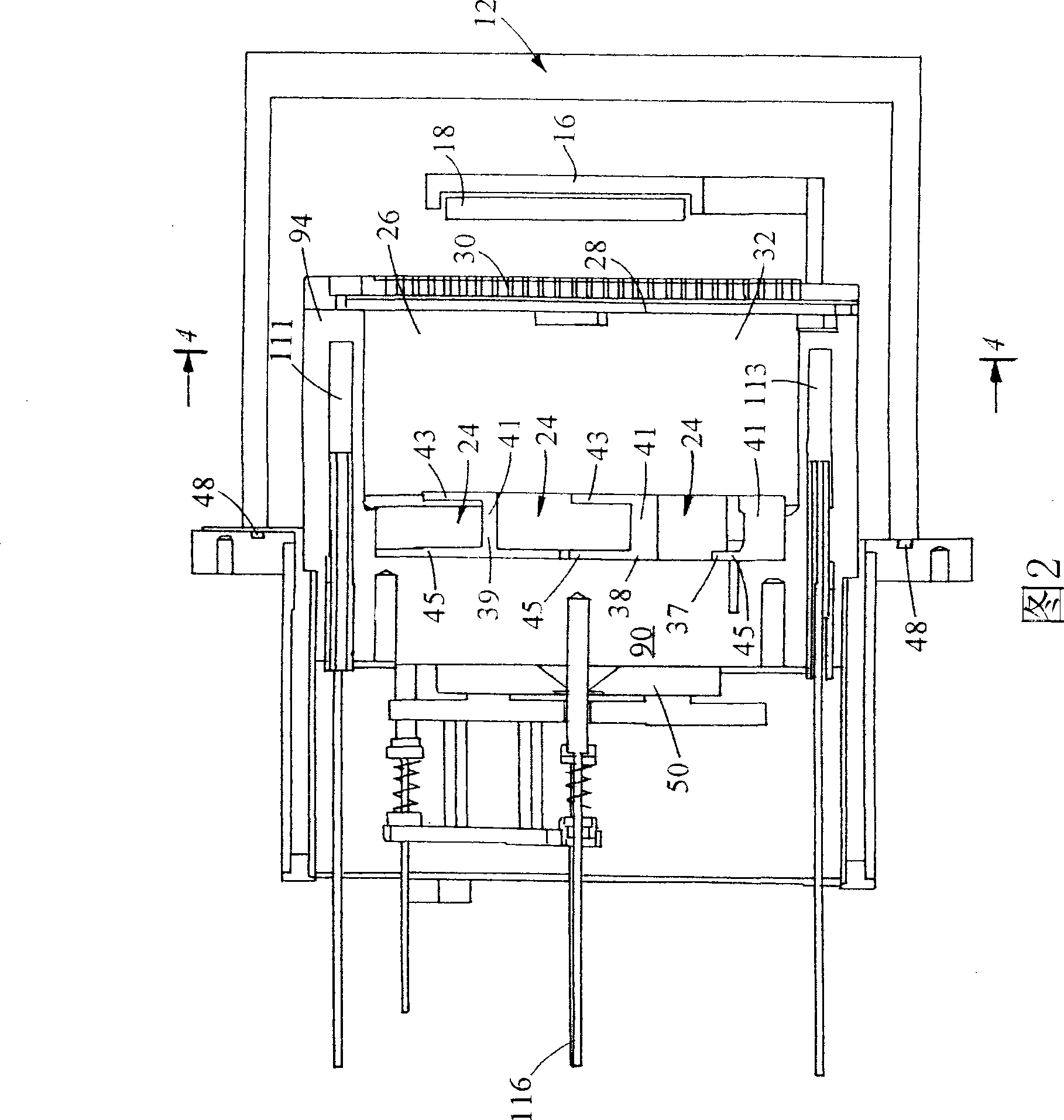
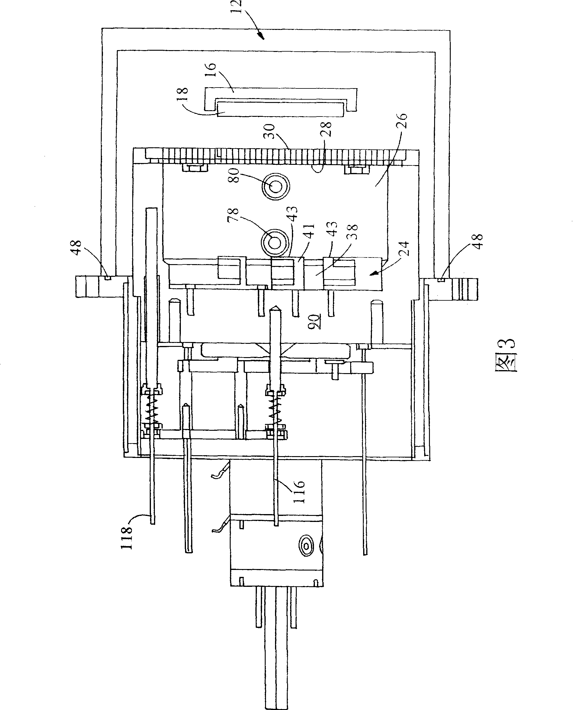
[0020] Reference is now made to the drawings containing a source 10 of lubricant (commonly referred to as oil) and a housing 12 containing a vacuum chamber 14 maintained at a suitable vacuum pressure by a suitable vacuum pump (not shown). Located in the chamber 14 is a holder 16 for a rigid magnetic disk 18 comprising a substrate covered alternately by layers of chromium and magnetic layers, as disclosed in the aforementioned patent. Subsequently, the holder 16 lifts the different rigid disks from the cassettes that move in and out of the vacuum chamber 14 to move the disks as figure 1 The location shown in -3, is deposited in the channel of the lubricant vapor on the disc. The lubricant is preferably PFPE.

[0021] Source 10 comprises an atmospheric portion 20 maintained at atmospheric pressure and a vacuum portion 22 maintained to have the same vacuum as in chamber 14 by a gas flow path often present between vacuum portion 22 and chamber 14. of vacuum pressure. A liquid l...


PUM


Abstract

Lubricant coatings are applied as lubricant vapor to magnetic disks 18 in a lubricant vapor flow path between the disks and a reservoir 24 for liquid lubricant that is heated to the vapor. The flow path includes a vapor chamber between the reservoir and an apertured diffuser 30. Plural piezoelectric crystals selectively, at different times, monitor the flow rate of lubricant vapor flowing in the vapor chamber, a result achieved by selectively positioning a shutter 28 that is selectively opened and closed between the vapor flowing in the vapor chamber and the crystals. Temperature variations of the crystals are compensated by a feedback arrangement for maintaining the crystal temperature constant.

Description

technical field [0001] The present invention generally relates to methods and apparatus for monitoring the mass flow rate of lubricant vapor through a vapor volume to a vacuum chamber. In it, a hard disk coated with a lubricant vapor is placed in the vacuum chamber. Background technique [0002] Hughes et al. in U.S. Patent 6,183,831 (hereby incorporated by reference) disclose a method for producing lubricants by supplying a vapor lubricant, i.e., gaseous, to a magnetic layer on a disk in a vacuum chamber, (preferably the full Fluoropolyether (PFPE)) method and apparatus for coating a hard disk with a lubricant film. The disk is then mounted in the flow path of the vapor by a carrying blade that lifts the disk from the cassette that is transported in and out of the vacuum chamber. This vapor is obtained by supplying sufficient heat to the source liquid lubricant located in the vacuum chamber. The generated vapor flows through the gas diffuser plate before being directed o...

Claims


Application Information

Patent Timeline
Patent Type & Authority Applications(China)
IPC IPC(8): G11B5/84
CPCC23C14/543C23C14/12G11B5/8408G11B5/725G11B5/71G11B5/842G11B2220/2508Y10S428/90
Inventor 卡尔·彼得森肯尼思·埃姆斯
Owner INTERVIDEO
Why Eureka
Try Eureka