Polarization encoding method and apparatus based on semiconductor optical amplifier

A technology of an optical amplifier and an encoding method, which is applied in the field of optical fiber communication encoding, and can solve the problems such as the inability to meet high-speed optical communication and the slow response speed of the dynamic polarization controller.

Inactive Publication Date: 2009-02-25
BEIJING JIAOTONG UNIV
View PDF1 Cites 13 Cited by
  • Summary
  • Abstract
  • Description
  • Claims
  • Application Information

AI Technical Summary

Problems solved by technology

But its disadvantages are: the response speed of the dynamic polarization controller is slow, on the order of microseconds, and the maximum modulation rate is only a few megahertz, which cannot meet the needs of high-speed optical communication

Method used


Image

  • Polarization encoding method and apparatus based on semiconductor optical amplifier
  • Polarization encoding method and apparatus based on semiconductor optical amplifier
  • Polarization encoding method and apparatus based on semiconductor optical amplifier

Examples


Embodiment 1

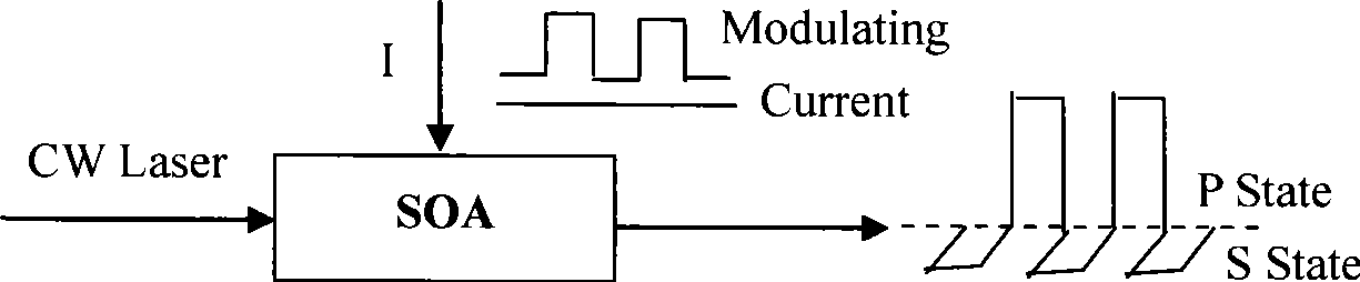
[0047] Example 1 figure 1 It is the schematic diagram of electrically controlled polarization rotation based on SOA. Such as figure 1 As shown, under the action of the modulating current, the polarization state of the output signal light can undergo orthogonal polarization rotation. Specifically, a stable DC laser (CW Laser) is introduced into the SOA, and the injection (or bias) current (I) is modulated to obtain the P-state and S-state polarization states, so that the polarization state of the output signal light appears in two Orthogonal polarization states. Due to the influence of the current on the gain of the SOA, the power of the two orthogonal polarization states is not equal.

Embodiment 2

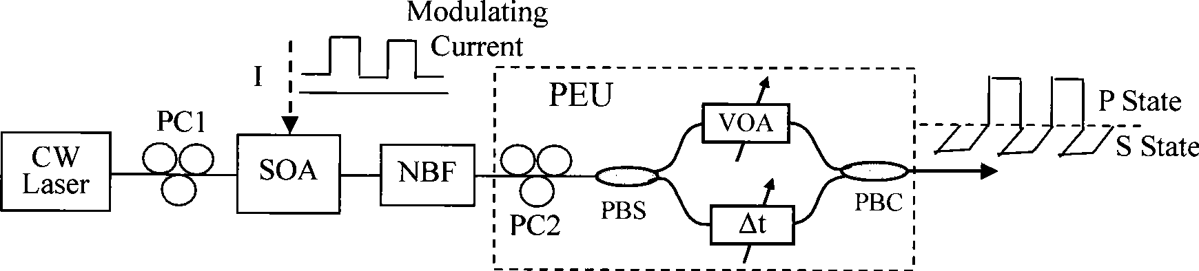
[0048] Embodiment 2 In an embodiment according to the present invention, an electronic control method is used to implement SOA-based power equalization polarization encoding. In this embodiment, a power equalization unit (PEU) based on single-path attenuation is used to achieve power balance, such as figure 2 As shown in , a stable DC laser (CW Laser) is introduced into the SOA, and the polarization state of the output signal light is rotated by orthogonal polarization by modulating the injection (or bias) current (I). Due to the gain effect of the injected current, the power of the output light will also change. For this reason, a power equalization unit (PEU) is used to achieve power balance, and a polarization beam splitter (PBS) and a polarization controller (PC2) are used to first divide the two orthogonal The polarized light is divided into two paths, and an attenuator (VOA) of appropriate size is added to the powerful path, and a phase compensator (Δt) is added to the ...

Embodiment 3

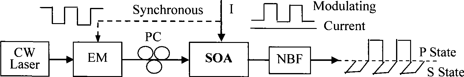
[0049] Embodiment 3 In an embodiment according to the present invention, such as image 3 As shown, the SOA-based power equalization polarization coding is realized by means of photoelectric synchronous control. In this embodiment, the synchronous method is used to control the input optical power in reverse to realize the power balance of the output optical signal. image 3 In this method, the power-balanced polarization encoding is achieved by synchronously controlling the injection current and input optical power of the SOA. When the current is a high pulse "1", the electrical signal applied to the EM modulating the input light is just the opposite to a low pulse "0". Due to the opposite rotation characteristics of the current and optical power, a larger polarization rotation angle can be obtained, and the output The optical power is stabilized at some predetermined value, and vice versa. In this photoelectric synchronous control method, the realization of photoelectric sy...


PUM


Abstract

The invention relates to a polarization encoding (PE) method based on a semiconductor optical amplifier (SOA) and a device thereof. The method uses the SOA to conduct polarization rotation, and realizes polarization encoding with power equilibrium by using the following three methods: (1) realizing power equilibrium through single channel attenuation by encoding with an electric control manner; (2) realizing polarization encoding with power equilibrium by using an optical-electric synchronous control manner; and (3) realizing power equilibrium through single channel attenuation by encoding with an optical control manner. Three corresponding polarization encoders are formed by using an orthogonal polarization encoding method based on the three encoding control methods. In the orthogonal polarization encoding method, S polarization state represents logic zero, and P polarization state represents logic one, and the powers of two orthogonal polarization optical pulses are same. The polarization encoders formed by using the inventive method have much faster encoding speed than conventional polarization encoders, and have the advantages of simple structure, convenient operation, and high practicability.

Description

technical field [0001] The invention relates to the technical field of optical fiber communication coding, in particular to a semiconductor optical amplifier (SOA)-based polarization coding method and device. Background technique [0002] The optical fiber communication coding technology generally uses the ON / OFF method based on light intensity to perform binary coding on the optical signal, that is, the presence of light (ON) represents logic "1", and the absence of light (OFF) represents logic "0". This encoding method is widely used because of its small technical difficulty and easy implementation, but the presence or absence of light intensity is realized by the gain and absorption of the medium. The energy in the light intensity OFF state is absorbed and converted into heat energy, and the processor needs to be refrigerated. The process stabilizes the temperature, which will reduce the processing speed, especially for those long-connected "0" signals, and the light inte...

Claims


Application Information

Patent Timeline
Patent Type & Authority Applications(China)
IPC IPC(8): H04B10/135G02F1/35
Inventor 李政勇吴重庆杨双收
Owner BEIJING JIAOTONG UNIV
Why Eureka
Try Eureka