Fixed device for microphone

A technology for fixing devices and microphones, applied in the field of microphones, can solve problems such as PCB shaking and PCB fixing, and achieve the effects of improving texture, avoiding complicated steps and simple structure.

Inactive Publication Date: 2009-02-25
MERRY ELECTRONICS CO LTD
View PDF0 Cites 0 Cited by
  • Summary
  • Abstract
  • Description
  • Claims
  • Application Information

AI Technical Summary

Problems solved by technology

[0006] Aiming at the deficiencies of the prior art, the purpose of the present invention is to provide a microphone fixing device. The technical problem to be solved is that the existing microphone fixing device cannot secure the PCB in order to achieve a thin and light shape, and the PCB is easy to fix. Vibration due to pulling on the microphone cable

Method used


Image

  • Fixed device for microphone
  • Fixed device for microphone
  • Fixed device for microphone

Examples


Embodiment Construction

[0024] Regarding the technology, means and effects used in the present invention, the following preferred embodiments are given below and described in detail with the accompanying drawings, which are for illustration purposes only, and are not limited by this structure in patent applications.

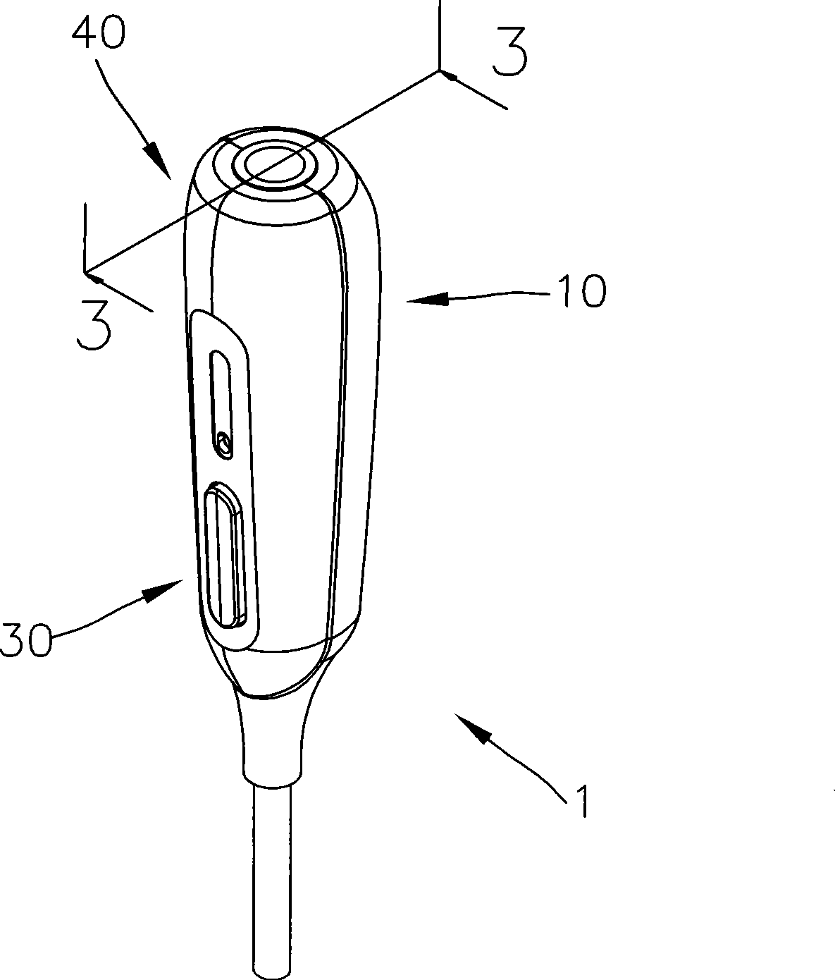
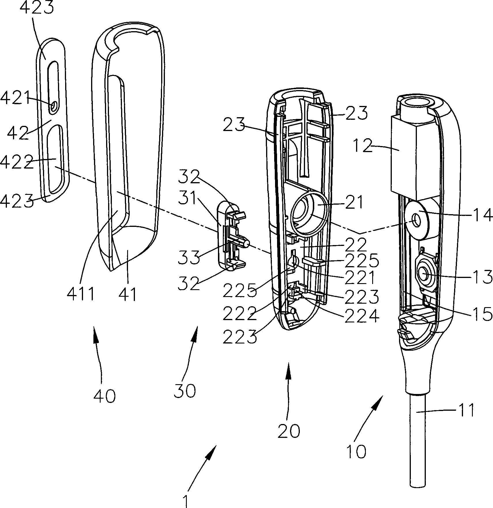
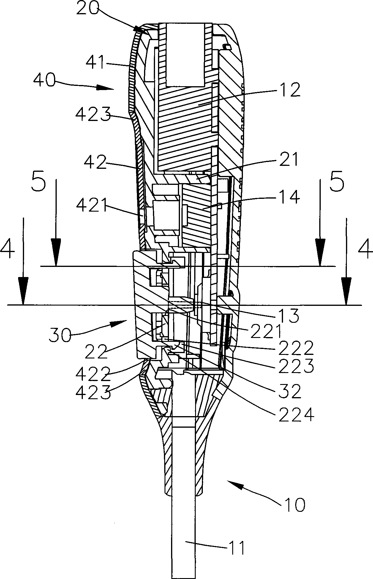
[0025] refer to Figure 1 to Figure 3 , are a perspective view, a perspective exploded view and a side sectional view of the microphone fixing device 1 of the present invention. The microphone fixing device 1 of the present invention includes a body 10 , a fixing base 20 , a button 30 and a housing 40 .

[0026] One end of the main body 10 is connected with a microphone line 11, and the other end is provided with a receiving portion 12 for receiving an earphone plug (not shown in the figure), a PCB 13 is provided adjacent to the microphone line 11, and a sound receiving device 14 is provided adjacent to the receiving portion 12. Used to receive sound. In addition, the inner walls on b...


PUM


Abstract

The invention is a microphone fixing device, which includes a body, a fixing base and a press button, wherein a PCB and a radio device are equipped in the body. The fixing device is equipped in the body, at the same time a touch hole is formed on the corresponding PCB, and each fixing rib is projected from each of the double-side of the fixing base wall surface, for pressing the PCB and limiting shakes between the body and the fixing base; and the press button passes through the touch hole and selectively presses the PCB, thereby controlling the open/close of the radio device.

Description

technical field [0001] The invention relates to a microphone, in particular to a microphone fixing device. Background technique [0002] Please refer to Figure 7 and Figure 8 , is a three-dimensional exploded view and a schematic cross-sectional view of the existing microphone fixing device 9 . Such as Figure 7 and Figure 8 As shown, the microphone fixing device 9 includes a body 91 , a fixing base 92 and a cover 94 . The body 91 is provided with a PCB911, the fixed seat 92 is clamped on the body 91, and the fixed seat 92 is provided with a number of holes 921 corresponding to the PCB911 for a button 93 to pass through, and the outer cover 94 is set on the fixed seat 92 and The body 91 can be covered. In addition, the cover 94 has a perforation 941 for the button 93 to protrude outside. In this way, the user presses the button 93 to touch the PCB 911 to control the opening / closing of the microphone fixing device 9. closure. [0003] Because the accommodating space o...

Claims


Application Information

Patent Timeline
Patent Type & Authority Applications(China)
IPC IPC(8): H04R1/04H04R1/08
Inventor 张瀞文谢芳昌魏文杰
Owner MERRY ELECTRONICS CO LTD
Why Eureka
Try Eureka