Vibration sensor

A vibration sensor and barrier technology, applied in the field of vibration sensors, can solve problems such as energy attenuation and reducing the sensitivity of condenser microphones

Inactive Publication Date: 2009-02-25
YAMAHA CORP
View PDF3 Cites 19 Cited by
  • Summary
  • Abstract
  • Description
  • Claims
  • Application Information

AI Technical Summary

Problems solved by technology

When the through hole of the package is closed by a film composed of polytetrafluoroethylene and sintered metal as disclosed in Patent Document 2, the energy of the sound wave transmitted through the film will be greatly attenuated, thereby reducing the sensitivity of the condenser microphone

Method used


Image

  • Vibration sensor
  • Vibration sensor
  • Vibration sensor

Examples


no. 1 example

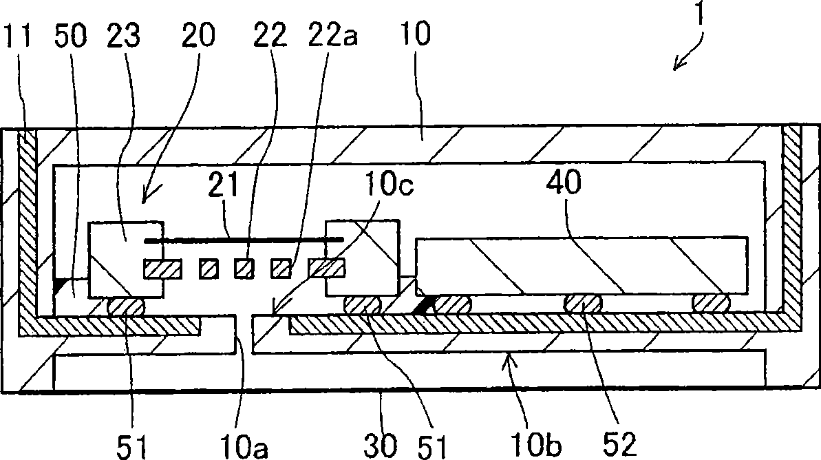
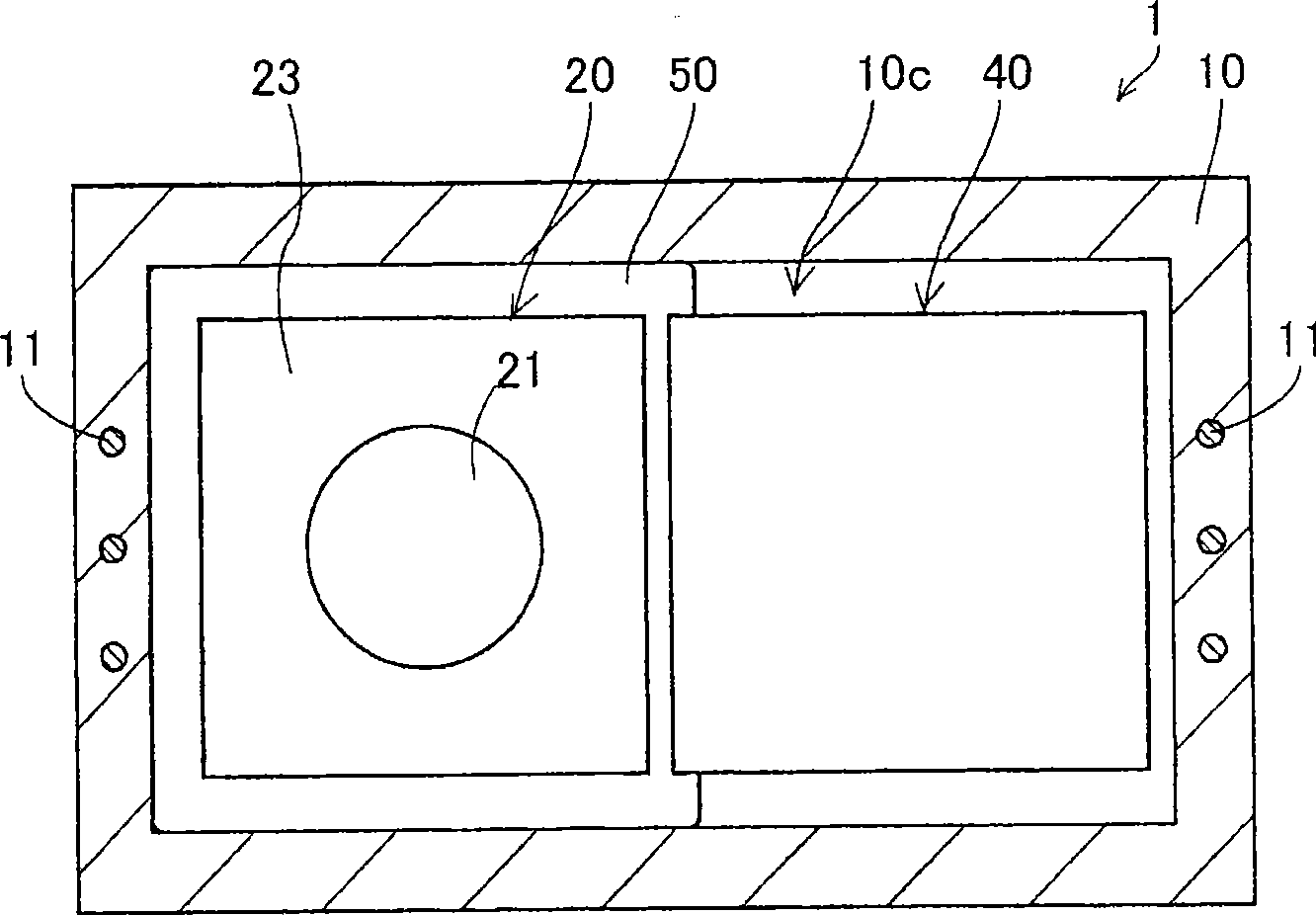
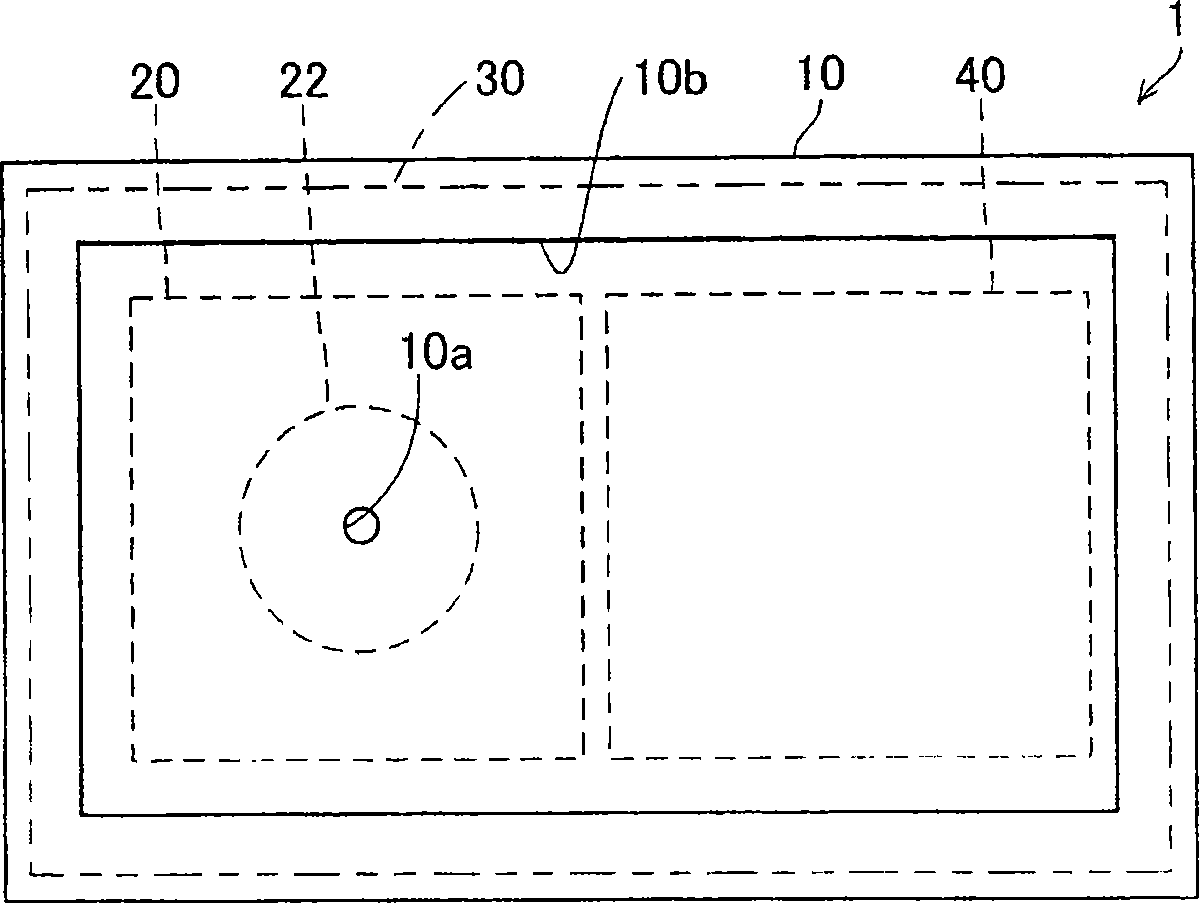
[0040] Figure 1A is a longitudinal sectional view of the vibration sensor, that is, a longitudinal sectional view of the condenser microphone 1 according to the first embodiment of the present invention. Figure 1B is a horizontal cross-sectional view of the condenser microphone 1 . Figure 1C It is a rear view of the condenser microphone 1 with the barrier diaphragm 30 removed.

[0041] The condenser microphone 1 of the first embodiment is a miniature condenser microphone used as a MEMS sensor, which is mounted in a portable electronic device such as a cellular phone. Specifically, the condenser microphone 1 is composed of a microphone die 20 serving as a vibration conversion die, an amplifier die 40 , and a case 10 for accommodating them and a barrier diaphragm 30 for covering the through hole 10 a of the case 10 .

[0042] The housing 10 has a box-like shape formed to accommodate the microphone die 20 and the amplifier die 40 . The case 10 is composed of a sealing material...

no. 3 example

[0088] Figure 4A is a longitudinal sectional view of a condenser microphone 3 which is a vibration sensor according to a third embodiment of the present invention. Figure 4B is a horizontal sectional view of the condenser microphone 3 with the barrier diaphragm 31 removed from its rear side.

[0089] In general, it is preferable to minimize the gap between the barrier diaphragm and the outer surface of the housing in accordance with the vibration of the barrier diaphragm. In the third embodiment, the vibrating membrane 31 is positioned to tightly close the conical recess (or conical recess) of the housing 12 (having the through hole 10a). The barrier diaphragm 31 has an axially symmetric vibration mode in a lower frequency range below its resonance frequency. That is, the amplitude of the barrier diaphragm 31 becomes smaller in the direction from the vibration axis BA (corresponding substantially to the center of the barrier diaphragm 31 ) to the vibration end terminal (co...

no. 4 example

[0091] Figure 5 is a longitudinal sectional view of a condenser microphone 4, which is a vibration sensor according to a fourth embodiment of the present invention. Compared with the condenser microphone 1 , the condenser microphone 4 has a housing 13 having a through hole 10 a covered by a barrier diaphragm 30 . In order to bring the barrier diaphragm 30 into contact with the outer surface 13 b of the housing 13 , a plurality of protrusions 13 d disposed on the opposite side of the barrier diaphragm 30 are formed on the outer surface 13 b of the housing 13 . Instead, only a single protrusion 13d may be formed at a designated area of ​​the outer surface 13b of the housing 13, which may easily come into contact with the barrier diaphragm 30 with a relatively high probability. That is, the number and positions of the protrusions 13d can be optimally determined on the basis of the characteristics and dimensions of the barrier diaphragm 30 .


PUM


Abstract

The invention provides a vibrating sensor (such as a condenser microphone) with high sensitivity, which is composed of a housing, a vibrating converter tube core and a barrier vibrating film, characterized in that the housing is made of sealing material and has through holes, the vibrating converter tube core is connected to inner surface of the housing around an assigned position of the through holes in a plane figure, the barrier vibrating film is made of sealing material and outer edge thereof is connected to outer surface of the housing opposite to the assigned position by means of sealing; the barrier vibrating film has a vibrating area bigger than section area of the through holes; a space permitting vibration of the barrier vibrating film is formed between outer surfaces of the barrier vibrating film and the housing, the distance between which may gradually reduce from a vibrating shaft to the outer edge.

Description

technical field [0001] The present invention relates to a vibration transducer and in particular to a miniature vibration transducer, such as a condenser microphone used as a MEMS (Micro-Electro-Mechanical Systems) sensor. Background technique [0002] In general, various types of miniature condenser microphones manufactured using a semiconductor device manufacturing process are known and disclosed in various documents such as Patent Document 1 and Patent Document 2 . [0003] Patent Document 1: Japanese Unexamined Patent Application Publication No. 2001-78297 [0004] Patent Document 2: Japanese Unexamined Patent Application Publication No. 2004-537182 [0005] A through-hole for propagating sound waves is formed in the housing of the miniature condenser microphone. In the condenser microphones disclosed in Patent Document 1 and Patent Document 2, the through holes are closed with fabric and a film composed of polytetrafluoroethylene and sintered metal. Fabrics and films...

Claims


Application Information

Patent Timeline
Patent Type & Authority Applications(China)
IPC IPC(8): H04R19/04
CPCH04R19/04
Inventor 铃木幸俊铃木利尚室井国昌永田达也
Owner YAMAHA CORP
Why Eureka
Try Eureka