
DC stepping permanent magnetism straight line motor drive type oil-submersible extracting pump

A permanent magnet linear motor and driven technology, which is applied in the direction of electric components, machines/engines, pumps, etc., can solve the problems of short service life of electric pumps, heavy workload, low motor efficiency, etc., and achieve low energy consumption and failure rate , reduced operating costs, and long service life

Inactive Publication Date: 2009-03-04
张洪新 +2
View PDF0 Cites 9 Cited by
  • Summary
  • Abstract
  • Description
  • Claims
  • Application Information

AI Technical Summary

Problems solved by technology

This kind of oil production device has mature technology, low failure rate and durability, but it needs to install a huge pumping unit on the ground and use a sucker rod of thousands of meters, and the system efficiency is low and energy consumption is high, especially for In wells with a certain inclination, eccentric wear of the sucker rod may occur, resulting in accidents such as damage and breakage of the sucker rod, and the workload of downhole operations is relatively large.
At present, the electric submersible pumps used in some oil areas are mainly composed of cables, submersible motors and centrifugal pumps with multi-stage impellers. This type of electric pump has a low head and is only suitable for shallow wells and oil wells with large production. Shortcomings such as low energy consumption, short service life of the electric pump, and high failure rate
In addition, although many types of downhole linear motors have appeared in the existing electric submersible pump mining technology, most of them are AC induction synchronous motors. When using them, the power frequency must be reduced, and the power is low and the thrust is small, which is not suitable for deep well oil production.

Method used


Image

  • DC stepping permanent magnetism straight line motor drive type oil-submersible extracting pump
  • DC stepping permanent magnetism straight line motor drive type oil-submersible extracting pump
  • DC stepping permanent magnetism straight line motor drive type oil-submersible extracting pump

Examples


Embodiment Construction

[0010] The implementation of the present invention will be further described below in conjunction with the accompanying drawings.

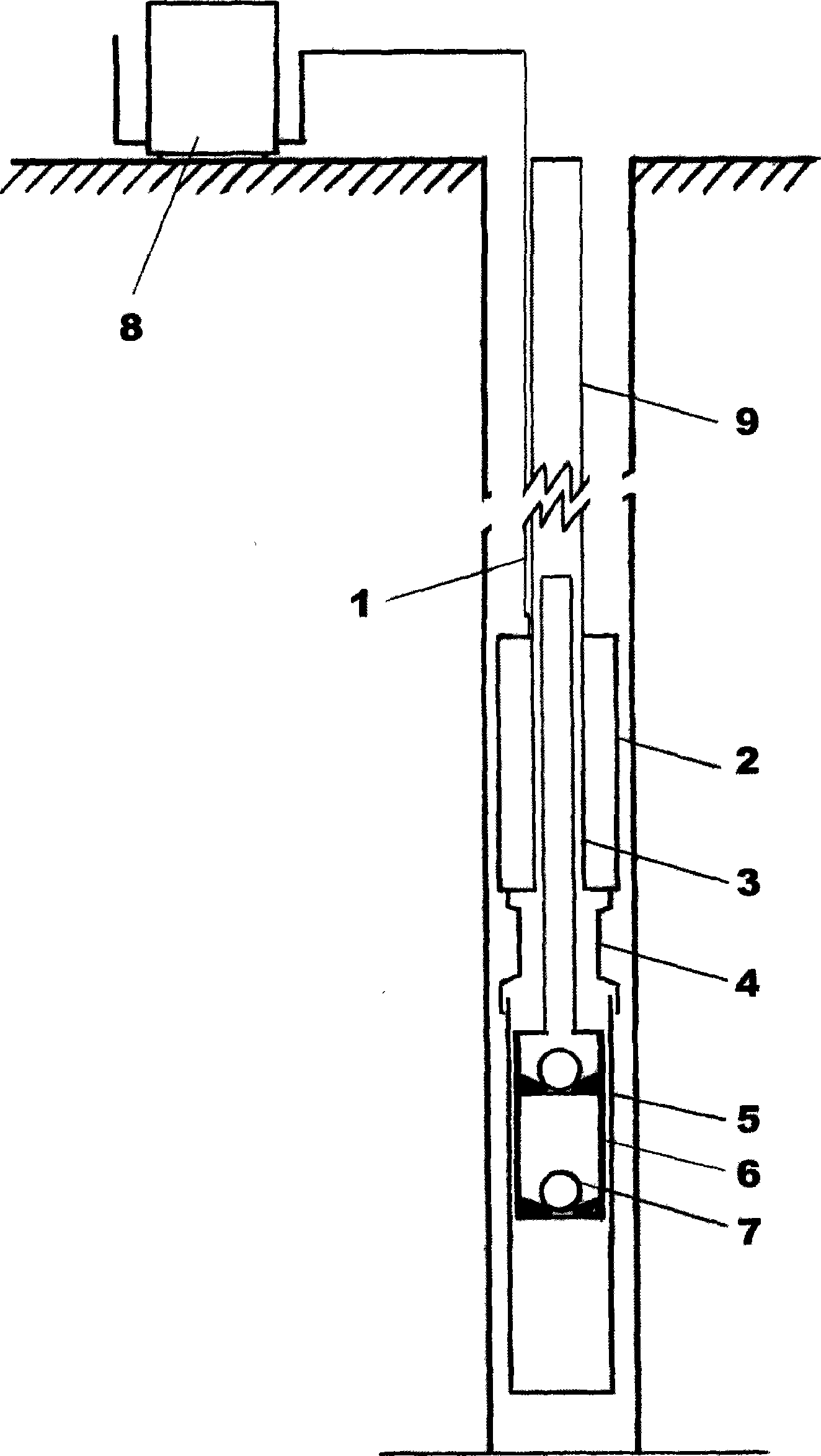
[0011] Such as figure 1 As shown, the present invention is made up of cable 1, motor barrel 2, motor mover 3, reducing sheath 4, pump barrel 5, plunger 6, ball valve group 7, and its structural assembly relationship is as follows: the upper and lower ends of cable 1 are respectively connected with The ground control cabinet 8 is connected to the coil in the motor barrel 2, the upper and lower ends of the motor barrel 2 are respectively connected with the oil pipe 9 and the variable diameter sheath 4 with threads, and the lower end of the variable diameter sheath 4 is connected with the pump barrel 5 with threads, The motor cylinder 2 and the pump cylinder 5 are respectively provided with a motor mover 3 , a plunger 6 and a ball valve group 7 , and the lower end of the motor mover 3 is connected with the upper end of the plunger 6 . Among them, th...


PUM


Abstract

The present invention relates to a submersible oil extraction pump driven by a direct-current magnetoelectric linear stepper motor. The oil extraction pump is composed of a cable (1), a motor cylinder (2), a motor mover (3), a diameter-variable sheath (4), a pump cylinder (5), a plunger (6) and a ball valve set (7); wherein, the upper and the lower ends of the cable (1) are respectively connected with coils arranged in a ground control cabinet (8) and the motor cylinder (2); the upper and the lower ends of the motor cylinder (2) are respectively connected with an oil pipe (9) and the diameter-variable sheath (4) by means of threads; the lower end of the diameter-variable sheath (4) is connected with the pump cylinder (5) by means of threads; the motor mover (3), the plunger (6) and the ball valve set (7) are respectively arranged in the motor cylinder (2) and the pump cylinder (5); and the lower end of the motor mover (3) is connected with the upper end of the plunger (6). With a novel structure, the oil extraction pump rejects the complex, large ground oil extraction pump and the 1000-meter sucker rod and can avoid the eccentric abrasion of the sucker rod and reduce operation cost. Compared with the prior centrifugal electric submersible pump, the oil extraction pump has the advantages of low energy consumption and fault rate, long service life, etc. and can be used in a deep well.

Description

technical field [0001] The invention relates to a downhole device used for oil exploitation in an oil field, which belongs to the category of oil production machinery and equipment. Background technique [0002] For a long time, the oil extraction equipment used in the oil field has been mainly beam or chain pumping units and downhole pumps. This kind of oil production device has mature technology, low failure rate and durability, but it needs to install a huge pumping unit on the ground and use a sucker rod of thousands of meters, and the system efficiency is low and energy consumption is high, especially for In wells with a certain inclination, eccentric wear of the sucker rod may occur, resulting in accidents such as damage and breakage of the sucker rod, and the workload of downhole operations is relatively large. At present, the electric submersible pumps used in some oil areas are mainly composed of cables, submersible motors and centrifugal pumps with multi-stage imp...

Claims


Application Information

Patent Timeline
Patent Type & Authority Applications(China)
IPC IPC(8): F04B47/12F04B47/00H02K41/03
Inventor 张洪新夏德权张越
Owner 张洪新
Learn More