Rubber sheet material for water stop, branch pipe connection configuration and construction method thereof
A rubber sheet and pipe connection technology, applied in the direction of pipes/pipe joints/fittings, pipes, branch pipelines, etc., can solve problems such as difficult operation and movement, and achieve the effects of labor saving, shortening and reliability
- Summary
- Abstract
- Description
- Claims
- Application Information
AI Technical Summary
Problems solved by technology
Method used
Image
Examples
no. 1 Embodiment approach
[0030] Hereinafter, the first embodiment embodying the present invention will be described in detail.
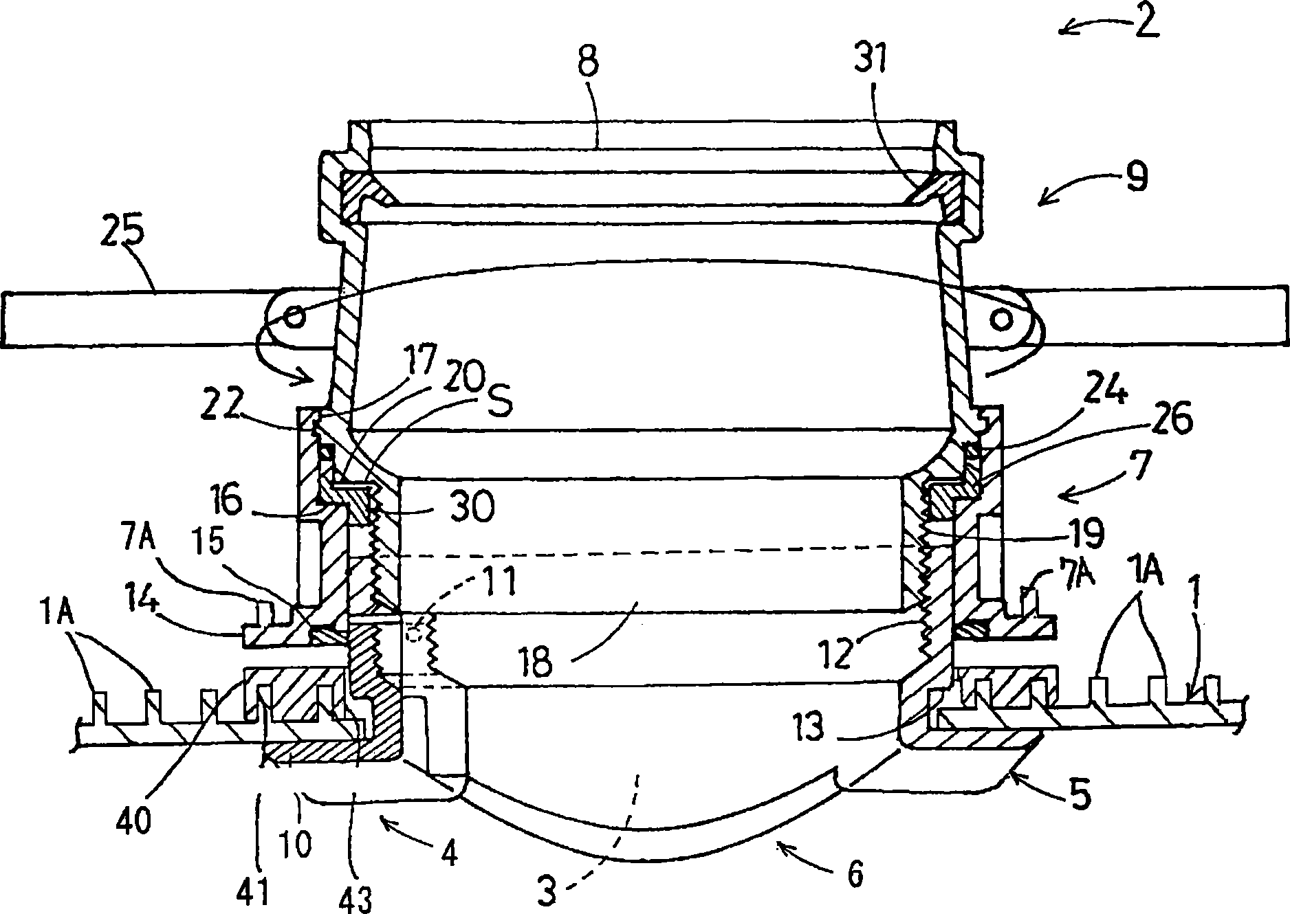
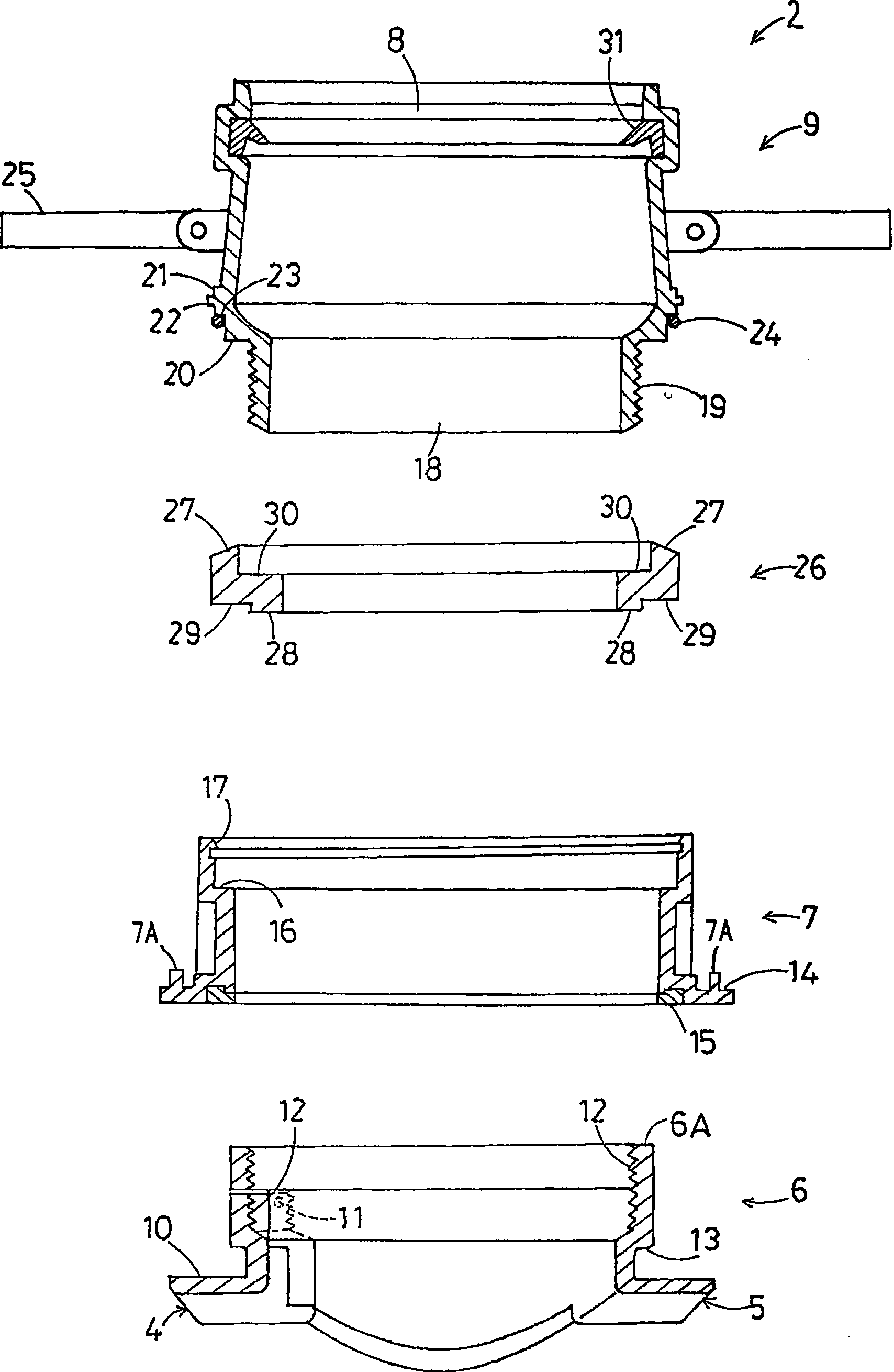
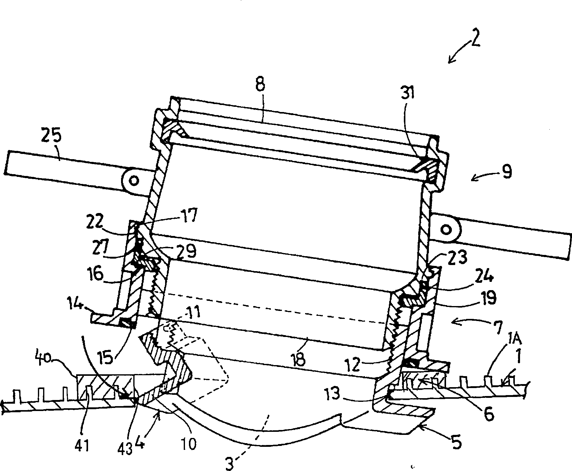
[0031] In each household, a branch pipe (not shown) constituting a branch pipe connected to a common tank (not shown) is connected to a sewage main pipe which is a main pipe constituting the main pipe. In order to connect the branch pipe to the sewer main pipe 1, the connecting branch pipe 2 is installed on the sewer main pipe 1 and used (refer to Figure 4 ).
[0032] As the above-mentioned sewage main pipe 1, a plurality of annular ribs 1A are juxtaposed on its outer peripheral surface, and a material that improves the strength and rigidity corresponding to the buried soil is used (refer to image 3 ). In addition, the sewage main pipe 1 is provided with a main pipe opening 3 for attaching the above-mentioned connecting branch pipe 2.
[0033] In addition, the main pipe opening 3 is usually formed by a hole tapping machine used as a work tool at the work site while considering...
no. 2 Embodiment approach
[0071] Figure 7 and Figure 8 This shows the second embodiment of the present invention.
[0072] In this embodiment, the pressing member 26 used in the first embodiment is not used, and instead of the pressing member 26, two parts composed of an upper step surface 27A and a lower step surface 28A are integrally protruding from the inner circumference of the saddle member 7. Step flange portion 26A. In addition, the contact step portion 16 of the saddle member 7 is omitted.
[0073] In the state where the connecting member 9 is screwed to the locking member 6, it is sandwiched between the stepped surface 23 of the flange portion 21 of the connecting member 9 and the upper stepped surface 27A of the secondary flange portion 26A of the saddle member 7 The spacer 24 is not pinched by the step surface 23 and the upper step surface 27A, and there is a gap S between the lower step surface 28A of the two-step flange portion 26A and the locking step surface 20 of the connecting member 9...
no. 3 Embodiment approach
[0076] Picture 9 with Picture 10 This shows the third embodiment of the present invention.
[0077] In this embodiment, the pressing member 26 used in the first embodiment is not used, and instead of the pressing member 26, the upper edge of the locking member 6 is extended and integrally formed by the upper peripheral surface 27B, the stepped portion 28B, and the lower surface. The pressing portion 26B constituted by 29B.
[0078] In the above configuration, the insertion portion 18 of the connecting member 9 is first inserted into the saddle member 7 from the upper side, and the lower surface 29B of the pressing member 26B of the locking member 9 is suspended on the abutting step 16 of the saddle member 7. on. In this state, the underside of the gasket 24 fitted directly under the step surface 23 of the flange portion 21 of the connecting member 9 is opened, and is fixed to the outer periphery of the connecting member 9 by the elastic binding force of the gasket 24. Therefore...
PUM
 Abstract
Description
Claims
Application Information
 - R&D
- Intellectual Property
- Life Sciences
- Materials
- Tech Scout
- Unparalleled Data Quality
- Higher Quality Content
- 60% Fewer Hallucinations
Browse by: Latest US Patents, China's latest patents, Technical Efficacy Thesaurus, Application Domain, Technology Topic, Popular Technical Reports.
© 2025 PatSnap. All rights reserved.Legal|Privacy policy|Modern Slavery Act Transparency Statement|Sitemap|About US| Contact US: help@patsnap.com


