Eureka AIR delivers breakthrough ideas for toughest innovation challenges, trusted by R&D personnel around the world.

Exhaust gas treatment system and exhaust gas treatment method

A technology for waste gas treatment and waste gas, which is applied in separation methods, chemical instruments and methods, and solid waste removal, etc., and can solve the problems of insufficient and excessive fly ash treatment agents.

Active Publication Date: 2021-08-24
KURITA WATER INDUSTRIES LTD
View PDF11 Cites 0 Cited by
  • Summary
  • Abstract
  • Description
  • Claims
  • Application Information

AI Technical Summary

Problems solved by technology

[0005] Sometimes, a fixed amount of such fly ash treatment agent is added for each batch of fly ash treatment or for each specific amount of fly ash, but in this case, the optimal amount of fly ash treatment agent for treatment of fly ash The ash properties of fly ash fluctuate. Therefore, in the case of adding a fixed amount of fly ash treatment agent, even if a specific amount of fly ash is treated, the fly ash treatment agent is effective for the harmless treatment of fly ash. There may also be insufficient or excessive

Method used


Image

  • Exhaust gas treatment system and exhaust gas treatment method

Examples


Embodiment Construction

[0023] Hereinafter, specific embodiments of the present invention will be described in detail, but the present invention is not limited to any of the following embodiments, and can be appropriately modified within the scope of the purpose of the present invention.

[0024]

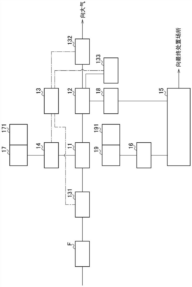
[0025] figure 1 A schematic flowchart of a construction example of the exhaust gas treatment system according to the present embodiment is shown. In addition, in figure 1 In , the solid line among the lines connecting the blocks represents the flow of objects, and the dotted line represents the flow of information.

[0026] The exhaust gas treatment system 1 involved in this embodiment is mainly composed of an exhaust gas treatment unit 11, a fly ash recovery unit 12, an exhaust gas treatment agent addition management unit 13, an exhaust gas treatment agent supply unit 14, a fly ash treatment unit 15, and a fly ash treatment agent supply unit. 16 and a fly ash treatment agent storage unit 19 constitute...


PUM


Abstract

The purpose of the present invention, on the premise of being an exhaust gas treatment system for using an exhaust gas treatment agent to treat an exhaust gas produced in the incineration of waste and then using a fly ash treatment agent to treat recovered fly ash, is to: eliminate the complexity of managing the stock quantity and controlling the addition amount of the fly ash treatment agent, thus saving labor; and avert a stock exhaustion (shortage) of the fly ash treatment agent. This exhaust gas treatment system is provided with: an exhaust gas treatment unit; a fly ash recovery unit; an exhaust gas treatment agent addition management unit provided to at least the upstream side from among the upstream side and the downstream side of the exhaust gas treatment unit, the exhaust gas treatment agent addition management unit analyzing the amount of acid contained in the exhaust gas, calculating the addition amount of the exhaust gas treatment agent at which the amount of alkali contained in the fly ash becomes within a prescribed range, and issuing a command to supply the exhaust gas treatment agent in the calculated addition amount; an exhaust gas treatment agent supply unit for supplying, to the exhaust gas treatment unit, the exhaust gas treatment agent in the addition amount according to the command issued by the exhaust gas treatment agent addition management unit; a fly ash treatment unit; and a fly ash treatment agent supply unit for supplying, to the fly ash treatment unit, the fly ash treatment agent at a given mass ratio relative to the fly ash loaded into the fly ash treatment unit.

Description

technical field [0001] The present invention relates to an exhaust gas treatment system and an exhaust gas treatment method. More specifically, it relates to a method capable of setting a fixed amount of a fly ash treatment agent required for treating fly ash recovered from exhaust gas and eliminating the need for stockpiling. Managers regularly check exhaust gas treatment systems and exhaust gas treatment methods that are complicated in management such as inventory. Background technique [0002] Exhaust gas from incineration of waste is an acidic gas containing hydrogen chloride and sulfur oxides. Conventionally, after treating such exhaust gas with an exhaust gas treatment agent such as slaked lime and sodium bicarbonate, the fly ash, which is a solid matter, is dedusted using a dust collector such as a bag filter, and then discharged from a chimney. [0003] On the other hand, fly ash recovered from dust collectors may contain heavy metals such as lead, cadmium, arsenic,...

Claims


Application Information

Patent Timeline
Patent Type & Authority Applications(China)
IPC IPC(8): B01D53/50B01D53/68B01D53/83B09B3/00
CPCB01D53/50B01D53/83B09B3/00B01D53/68Y02W30/91
Inventor 水品惠一山崎武志米山健太郎
Owner KURITA WATER INDUSTRIES LTD
Why Eureka
Eureka Blog
Learn More