Manufacturing method for pipe structure

A manufacturing method and structure technology, applied in the field of tube structures, can solve problems such as inability to eliminate defects

Pending Publication Date: 2021-03-26
NORITZ CORP
View PDF4 Cites 0 Cited by
  • Summary
  • Abstract
  • Description
  • Claims
  • Application Information

AI Technical Summary

Problems solved by technology

Thus, the undesirable situation described cannot be eliminated

Method used


Image

  • Manufacturing method for pipe structure
  • Manufacturing method for pipe structure
  • Manufacturing method for pipe structure

Examples


Embodiment Construction

[0041] Preferred embodiments of the present invention will be specifically described below with reference to the drawings.

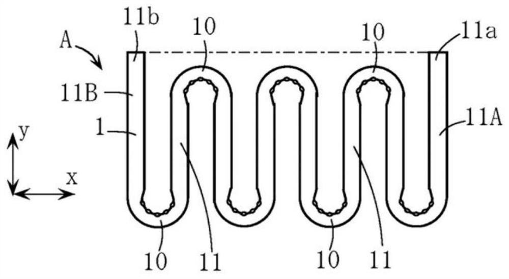
[0042] The manufacturing object of the manufacturing method of the pipe structure of this embodiment is the same as the already described prior art. figure 1 The serpentine tubular body A shown. Therefore, the same reference numerals as those of the above-mentioned prior art are attached to the same or similar elements as those of the above-mentioned prior art.

[0043] First, the serpentine tubular body A will be described.

[0044] As already described, the serpentine pipe body A is formed by, for example, a stainless steel pipe 1 formed in a serpentine shape, has a plurality of bent portions 10 with a bending angle of 180 degrees, and is formed by these plurality of bends. A plurality of linear portions 11 connected to each other. Areas 11A, 11B near both ends of the pipe 1 are figure 1 It is separated in the widthwise direction of the x-direction...


PUM


Abstract

A manufacturing method for a pipe structure includes a pipe bending step for implementing for a plurality of times a bending process of bending a part of a straight pipe (1) by wrapping the part around a peripheral surface of a rolling block (2) to form a plurality of bend portions (10) in intermediate locations along a longitudinal direction of the pipe. When a final bending process is implemented during the pipe bending step, a position of a rear end portion (11b) of the pipe (1) is determined, and relative positions of the pipe (1) and the rolling block (2) in a predetermined y direction are controlled on the basis of the position of the rear end portion (11b) so that after the bending process, a y-direction position of the rear end portion (11b) is aligned with a y-direction position of the front end portion (11a). According to this configuration, complicated operations such as cutting the respective end portions (11a, 11b) of the pipe (1) after bending the pipe (1) can be eliminated, and a pipe structure such as a meandering pipe body (A) in which the positions of the respective end portions (11a, 11b) are aligned can be manufactured appropriately and with favorable productivity.

Description

technical field [0001] The present invention relates to a method for producing, for example, a meandering or spiral tube structure used as a component of a heat exchanger or the like. Background technique [0002] As a tube structure used as a heat transfer tube of a heat exchanger, there are, for example figure 1 The serpentine tubular body A shown. This meandering pipe body A is formed by forming a stainless steel pipe 1 into a meandering shape, and has a plurality of bent portions 10 . Regions 11A and 11B near both ends of the tube 1 are separated in the x direction and extend along the y direction intersecting the x direction. [0003] As a method of manufacturing the serpentine tubular body A, for example, there are Figure 12 method shown. This manufacturing method has a pipe making and punching and cutting step S1, a pipe bending step S2, and a cutting and burr removal step S3. [0004] Here, the pipe making and stamping and cutting process S1 is a process such a...

Claims


Application Information

Patent Timeline
Patent Type & Authority Applications(China)
IPC IPC(8): B21D7/14B21D53/06F28D7/02F28D7/08
CPCB21D7/14B21D53/06F28D7/082F28D7/02B21D11/06B21D53/027B21D7/025B21D7/028
Inventor 瀬直己寺泽太平奥田丞志藤泽秀行古山元士
Owner NORITZ CORP
Why Eureka
Try Eureka