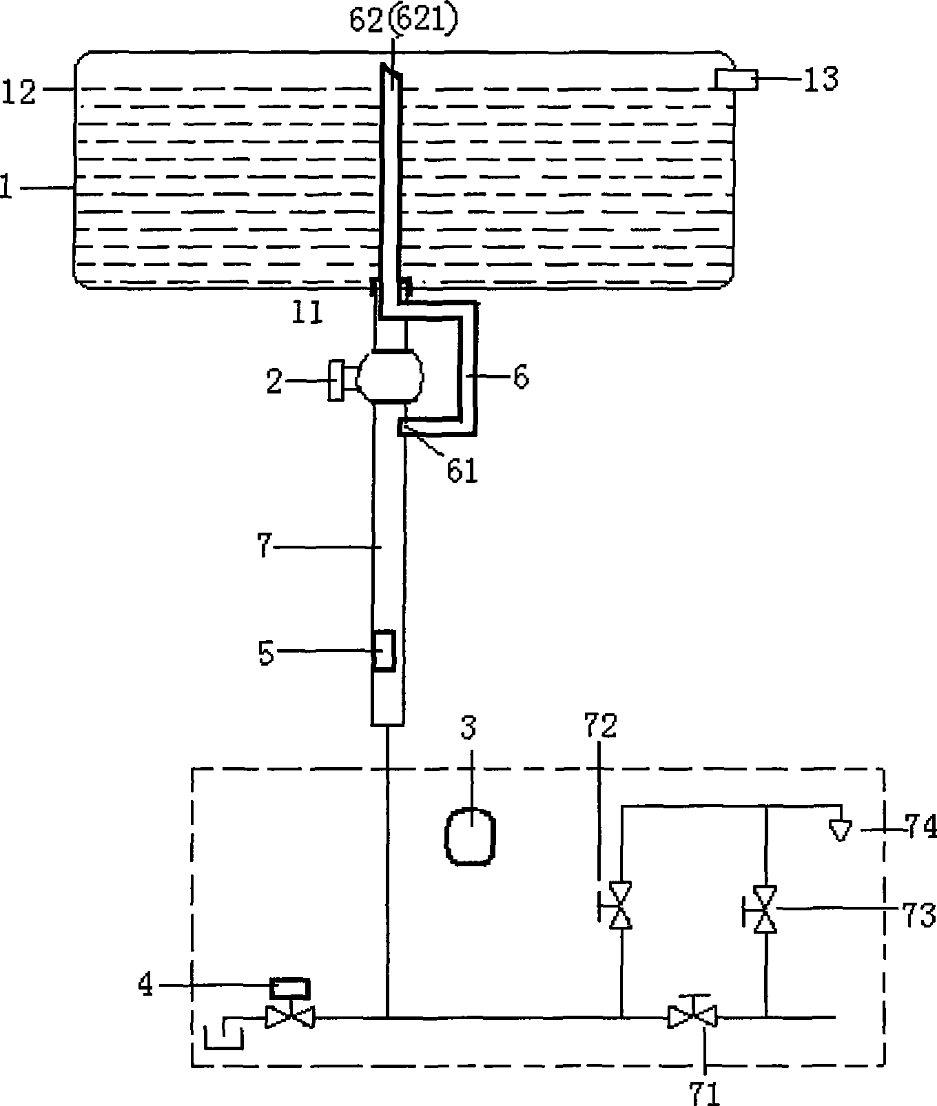
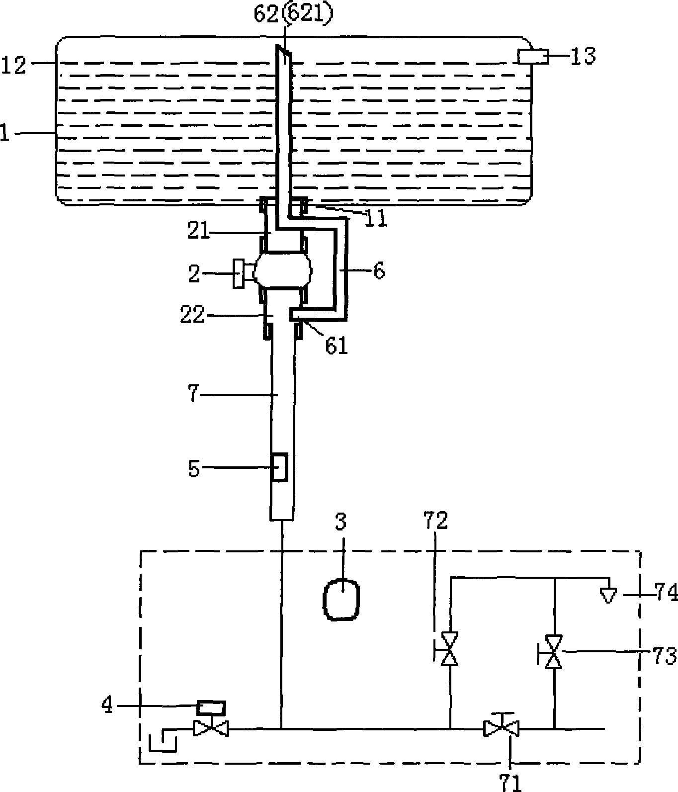
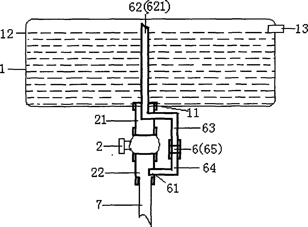
[0025] like figure 1 , 2 Shown is the basic composition structure of the present invention. The water-saving anti-freezing device is set in a solar water heater system composed of a water storage tank 1, an electric control valve 2, an intelligent controller 3, an electric valve for draining water 4, a temperature sensor 5, and indoor and outdoor connecting pipes and valves. The device is mainly composed of an electric control valve 2 and a bypass air guide pipe 6, and is located below the water storage tank 1. The upper and lower ports of the electric control valve 2 are respectively provided with an upper connector 21 and a lower connector 22, the upper end of the upper connector is connected with the water inlet and outlet 11 of the water storage tank, and the lower end of the lower connector is connected with the main pipeline 7; the bypass guide The lower port 61 of the trachea communicates with the lower connector, and its upper port 62 passes through the upper connector and enters the water storage tank, and its port is exposed above the overflow surface 12 of the water body of the water storage tank, and passes through the water storage tank. The overflow pipe 13 communicates with the atmosphere. The upper port 621 of the bypass air guide pipe is inclined, exposed at 5-10 mm on the overflow surface 12 of the water body of the water storage tank. In addition: the inner cavity set by the electric control valve 2 is a straight-through hole, and the preferred inner diameter range is 12-14 mm; the bypass air guide tube is a copper tube or a stainless steel metal tube, and the outer diameter is not greater than 8 mm, and the inner diameter is 2-14 mm. between 6 mm. The present invention sets the electric valve 4 for discharging water at the lowest point of the water inlet and outlet main pipeline 7 in the user's room (represented by a dotted line frame among the figures). In addition, the indoor is also provided with a pipeline gate valve 71, a hot water switch 72, a cold water regulating switch 73 and a water appliance 74, and the intelligent controller 3 is installed at an appropriate position on the indoor wall. In order to accurately grasp the temperature of the connecting pipes of the system, a temperature sensor 5 is arranged on the main outdoor water inlet and outlet pipe 7 . In addition: the electric control valve 2, the water discharge electric valve 4, and the temperature sensor 5 of the present invention are all controlled by the intelligent controller 3, and implement the access and discharge of the system pipeline waterway.
[0026] like image 3 Shown is the first embodiment in which the bypass air duct 6 of the water-saving and anti-freezing device component of the present invention is arranged and installed in sections. As can be seen in the figure, the bypass airway 6 is divided into upper and lower sections, an upper section 63 and a lower section 64, and the two are welded into one body through a sleeve 65.
[0027] like Figure 4 Shown is the second embodiment in which the bypass air duct 6 of the water-saving and anti-freezing device component of the present invention is arranged and installed in sections. In this embodiment, the upper end section 66 of the bypass air duct passes through the upper connector 21 to the pipe section above the overflow surface is a metal pipe, and the bypass outer pipe section 67 is a rubber pipe, and the upper end of the rubber pipe and the metal pipe extend outward. The outlet interface is connected, and the lower end of the rubber tube is connected with the outer extension interface of the lower connector 22, and the joint is fastened by a jumper.
[0028] like Figure 5 Shown is the third embodiment in which the bypass air duct 6 of the water-saving and anti-freezing device component of the present invention is arranged and installed in sections. In this embodiment, the bypass air duct is composed of separate L-shaped metal pipe 68 and U-shaped metal pipe 69, and the L-shaped metal pipe crosses from the upper connector 21 to the overflow surface; the two U-shaped metal pipes The ends are 90-degree flanging, and the externally extending threaded interfaces with through holes in the centers of the upper and lower connectors are connected through nuts, and the joints are pressed tightly with rubber seals.
[0029] like Image 6 Shown is an embodiment of the connection mode between the component electric control valve and the upper and lower connectors of the water-saving and anti-freezing device of the present invention. In this embodiment, the upper and lower ends of the electric control valve 2 are respectively provided with positioning recesses, and rubber seals are arranged in the recesses. Lugs 24 and shoulders 25 are provided on the upper and lower connectors, and through holes are provided on the lugs, and the shoulders and the recesses are fitted accordingly. The upper and lower connectors and the electric control valve are fastened by bolts 26 passing through holes opened by the lugs.
[0030] like Figure 7 As shown, in this embodiment, a positioning member 27 is provided outside the upper connector, and components such as the electric control valve, the upper and lower connectors, and the bypass air guide tube are placed in the shell 28 for limit and fixation, and the The insulation layer of the water inlet and outlet 11 is provided with depressions, and the shell corresponding to the depressions is provided with shoulders, and the insulation material 8 is filled between the components. The thermal insulation material is polyurethane foam.
[0031] Below in conjunction with accompanying drawing, briefly describe the implementation process of function of the present invention:
[0032] (1) The system feeds water into the water storage tank 1:
[0033] Open the pipeline gate valve 71 and press the intelligent controller to close the water discharge electric valve 4, open the electric control valve 2, tap water enters the lower connector 22 along the pipeline, enters the water heater storage tank in two ways, and most of the water passes through the electric control valve and the upper water tank. The connector enters the storage tank; a small portion of the water enters the storage tank through the bypass air duct.
[0034] (2) Empty the main water inlet and outlet pipes 7 of the system:
[0035] When the water level of the water storage tank reaches the overflow control water surface, close the pipeline gate valve 71, press the intelligent controller to close the electric control valve 2, open the water discharge electric valve 4, the water in the main water inlet and outlet pipes is discharged into the sewer, and the air overflows from the water storage tank Enter through the mouth and fill the main pipeline through the bypass airway 6.
[0036] (3) Get hot water from the indoor water appliance 74:
[0037] Press the intelligent controller, open the electric control valve 2, close the water discharge electric valve 4, open the hot water switch 72, the hot water in the water storage tank enters the water inlet and outlet main pipeline 7 under the action of gravity, and the water supply utensil 74 takes.
[0038] (4) Low temperature antifreeze of the system:
[0039] When the ambient temperature of the system is low in winter, when the temperature sensed by the temperature sensor 5 installed on the main water inlet and outlet pipes may freeze (0°C), the intelligent controller will issue an instruction to close the electric control valve 2 and open it at the same time. The water discharge electric valve 4 is used to empty the water in the main pipeline, so as to ensure that the system will not be blocked by freezing or cracked by freezing in the cold winter in the north and south of the system, and hot water can be used normally.
[0040] (5) Water saving function of the system:
[0041] Every time the system feeds water into the water storage tank 1, it only needs to be emptied once. When it is used for many times afterwards, as long as the electric control valve 2 is opened, hot water will flow down. When the electric control valve is closed, the hot water in the pipeline will basically When it is exhausted, there is no cold water in the pipeline, and it is true that "there is hot water as soon as it is turned on", saving water and energy.
[0042] In summary, the present invention has achieved the expected purpose of the invention.