Rough element apparatus with variable rotary-out type wind tunnel

A rough element, screw-out technology, applied in measuring devices, testing of machines/structural components, instruments, etc., can solve problems such as time-consuming and labor-intensive, and achieve the effect of reducing workload

Inactive Publication Date: 2009-03-04
PEKING UNIV
View PDF0 Cites 15 Cited by
  • Summary
  • Abstract
  • Description
  • Claims
  • Application Information

AI Technical Summary

Problems solved by technology

In the existing wind tunnel experimental research, in order to form a suitable simulated atmospheric boundary layer, it is necessary to adjust or replace the height and distribution density of different types of rough elements according to the actual situation, which is time-consuming and labor-intensive.

Method used


Image

  • Rough element apparatus with variable rotary-out type wind tunnel
  • Rough element apparatus with variable rotary-out type wind tunnel
  • Rough element apparatus with variable rotary-out type wind tunnel

Examples


Embodiment 1

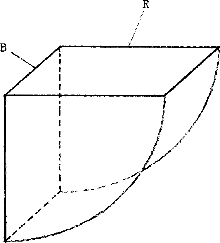
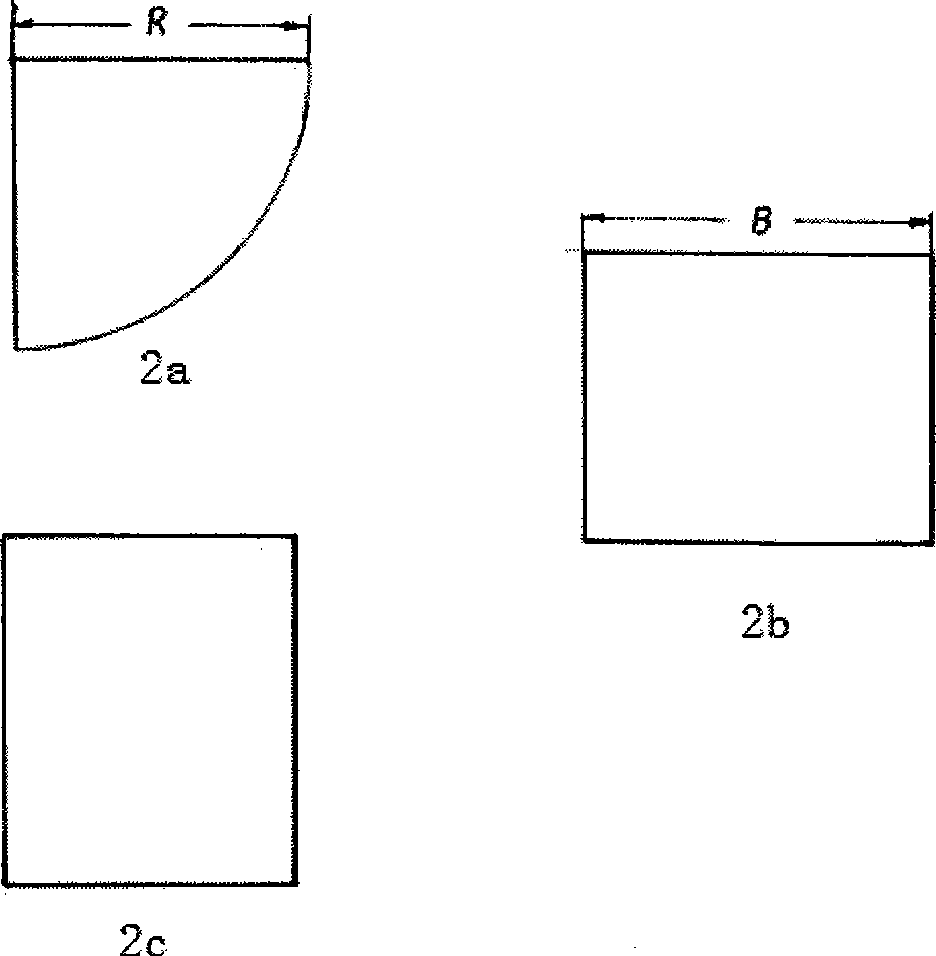
[0013] Example 1: The size of the rough element is as figure 1 , figure 2 and Figure 4 As shown, where the radius is R and the width is B, the distribution map of the rough elements is designed according to the experimental requirements, and a plurality of rough elements that meet the requirements are processed; the perforated plate and the lower plate (or frame) are processed for processing And easy to install, the whole screw-out variable roughness element device can be processed in sections and then butted together. Figure 4 It is a schematic diagram of the distribution of rough elements in the variable rough element device of the swing-out wind tunnel (only four rows are drawn), where R is the radius of the rough elements, B is the width of the rough elements; L is the row spacing, and S is the column spacing; the rough element installation When in the wind tunnel, its column direction is parallel to the wind tunnel axis.

Embodiment 2

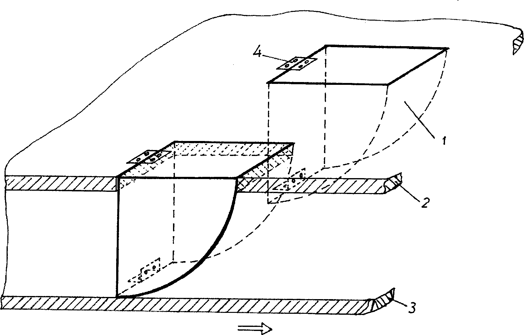
[0014] Example 2: image 3 It is a schematic diagram of the assembly of the variable rough element of the swing-out wind tunnel according to the present invention, wherein, 1 is a single rough element, 2 is a perforated plate, 3 is a lower plate, and 4 is a hinge. The arrow indicates the moving direction of the lower plate. This direction in the hole is usually also the direction of the airflow, but it can also be against the direction of the airflow. like image 3 As shown, the device consists of four main components: multiple rough elements, a perforated plate, a lower plate (or frame) and a hinge. The shape of the rough element is a quarter cylinder section, and the cylinder section is made of various materials such as wood, aluminum, and stainless steel. The purpose of making rough elements into a quarter cylindrical shell is to reduce the weight of each rough element, where the size (radius R, width B) and spacing of each rough element are determined by each wind tunnel...


PUM


Abstract

The invention provides a back-out type wind tunnel changeable rough element device, comprising four main units of a plurality of rough elements, a hole opening flat plate, a lower flat plate (or a frame) and a hinge. The device is characterized in that the shape of the rough element is a quarter cylindrical section. One straight edge of the rough element is hinged on the hole opening flat plate, and the other straight edge is hinged on the lower flat plate (or the frame) which is arranged under the hole opening flat plate and is parallel with the hole opening flat plate. The hole opening flat plate and the bottom plate of the wind tunnel are trimly fixedly installed, ensuring that the rough element can back out from the upper surface of the hole opening plate through moving the lower flat plate (or the frame) to one direction. The back-out amount of the rough element can be controlled through changing the moving amount of the lower flat plate, with the result that the roughness of the whole hole opening plate can be changed, and varieties of near surface air currents which simulate atmospheric boundary layer are formed in the wind tunnel. The device can realize the stepless regulation to the height of the rough element simply and quickly.

Description

technical field [0001] The invention relates to a variable rough element device of a swing-out wind tunnel, which belongs to the field of experimental aerodynamics. Background technique [0002] When carrying out wind tunnel experimental research on disciplines such as wind engineering and environmental fluid mechanics, it is necessary to form a certain type of simulated atmospheric boundary layer flow in the wind tunnel. The usual method is to place an appropriate type of wedge ( Tower) and rough elements. Rough elements are blocks distributed on the plane, most of which are cuboids. According to the type of simulated atmospheric boundary layer to be formed, the size and distribution density of rough elements need to be adjusted accordingly. For cuboid rough elements, usually adjust their Height and distribution density, or just adjust its height to meet the requirements. In the existing wind tunnel experimental research, in order to form a suitable simulated atmospheric ...

Claims


Application Information

Patent Timeline
Patent Type & Authority Applications(China)
IPC IPC(8): G01M9/04
Inventor 魏庆鼎王建明王亚利
Owner PEKING UNIV
Why Eureka
Try Eureka